


 Download PDF
DATASHEET SEARCH SITE
Document overview
- PDF pages: 2
Technical content
Page 1
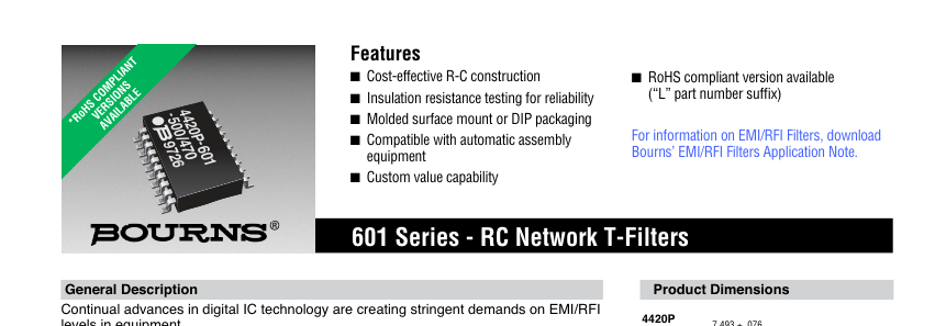
levels in equipment.
EMI/RFI low pass fi lters are required in personal computers, data terminals, test
equipment and process controllers for high frequency suppression into or out of
electronic equipment. Electrical Specifi cations - Resistors
Standard Resistance Range\* ...........................................................10 ohms - 100 ohms
Series Resistance Tolerance ................................................................................. ±10 %
Temperature Coeffi cient of Resistance ....................................................... ±300 ppm/°C
Operating Voltage ................................................................................ 25 volts maximum
Operating Temperatures ....................................................................... +10 °C to +85 °C
\*Other Resistance Values Available, 10 ohms - 1 megohm
Electrical Specifi cations - Capacitors
Standard Capacitance Range ................................................................50 pF to 200 pF
Capacitance Tolerance ........................................................................................... ±30 %
Temperature Characteristic .......................................................................................Z5U
Operating Temperatures ........................................................................ +10 °C to +85 °C
Voltage Rating ......................................................................................................25 volts
Dielectric Withstand Voltage ...............................................................2.5 x rated voltage
Insulation Resistance ...........................................................10,000 megohms minimum Environmental Specifi cations - Resistors
∆R MAXIMUM
Thermal Shock ..................................................................................................... ±0.5 %
Resistance to Solder Heat .................................................................................... ±0.5 %
Terminal Strength ................................................................................................. ±0.5 %
Mechanical Specifi cations
Flammability ..................................................................................Conforms to UL94 V-0
Leadframe .................................................................................... Copper, solder coated
Body Material............................................................................................ Epoxy/Novolac
Lead Solderability .................................Meet requirements of MIL-STD-202 Method 208
For Standard Values Used in Capacitors, Inductors, and Resistors, click here.
7.493 ± .076 (.295 ± .003)
.432 ± .056 TYP. (.017 ± .002) 10.34 ± .25 (.407 ± .010)
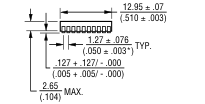
.305 + .000/ - .076 (.012 + .000/ - .003)
8° MAX. .940 + .355 (.037 ± .014)
4118R AND 4120R
.635 (.025) PIN #1 REF.
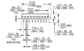
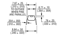
Governing dimensions are metric. Dimensions in parentheses are inches and are approximate.
\*Terminal centerline to centerline measurements made at point of emergence of the lead from the body.
\*RoHS Directive 2002/95/EC Jan. 27, 2003 including annex and RoHS Recast 2011/65/EU June 8, 2011.
Specifi cations are subject to change without notice.
The device characteristics and parameters in this data sheet can and do vary in different applications and actual device performance may vary over time.
Users should verify actual device performance in their specifi c applications.
Page 2
601 Series - RC Network T-Filters
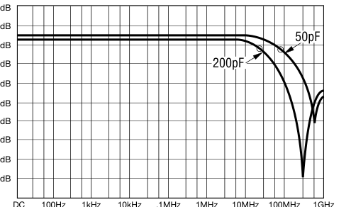
Attenuation Vs. Frequency - Typical Capacitor Values With R= 25 Ohms
Attenuation vs. Frequency
+5dB
Model 4120R-601-250/500 Model 4420-601-250/500 50pF - 3dB @ 84 MHz
-5dB
Attenuation vs. Frequency
-10dB
Model 4120R-601-250/201 Model 4420P-601-250/201
-15dB
200pF - 3dB @ 21 MHz
-20dB
-25dB
-30dB
-35dB
-40dB
indicates - 3dB rolloff frequency (f )
c
These low-pass fi lters are ideal for installation between I/O drivers and RS 232
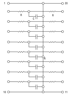
Typical Circuit
connectors.
4120R-601-RC/CC
How To Order EMI/RFI Filter Networks
4420R-601-RC/CC
44 20 P - 601 - RC/CC __
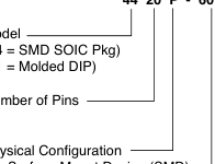
Model
P = Surface Mount Device (SMD) R = Molded DIP
Insert RC/CC Code from table below to form part number.
| RC | R | CC | C |
| 250 | 25 | 500 | 50 pF |
| 270 | 27 | 101 | 100 pF |
| 470 | 47 | 181 | 180 pF |
| 820 | 82 | 201 | 200 pF |
| 101 | 100 |
Consult factory for values not listed.
Terminations L = RoHS compliant (tin-plated) Blank = Tin-lead plated
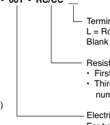
Resistance/Capacitance Code
- First 2 digits are signifi cant
- Third digit represents the number of zeros to follow Electrical Confi guration For tube packaging, use code “T06”
Packages Available 4420P-601-\*RC/CC-SMD 4120R-601-\*RC/CC-DIP 4118R-601-\*RC/CC-DIP
\*First two digits are signifi cant. Third digit represents the number of zeros to follow.
Seven circuits in an 18-pin package. Eight circuits in a 20-pin package.
REV. 09/14
Specifi cations are subject to change without notice.
The device characteristics and parameters in this data sheet can and do vary in different applications and actual device performance may vary over time.
Users should verify actual device performance in their specifi c applications.