

 Download PDF
DATASHEET SEARCH SITE
Document overview
- PDF pages: 14
Technical content
Page 1
Document Number: A3I20X050N
Rev. 2, 05/2020
Technical Data
RF LDMOS Wideband Integrated
Power Amplifiers
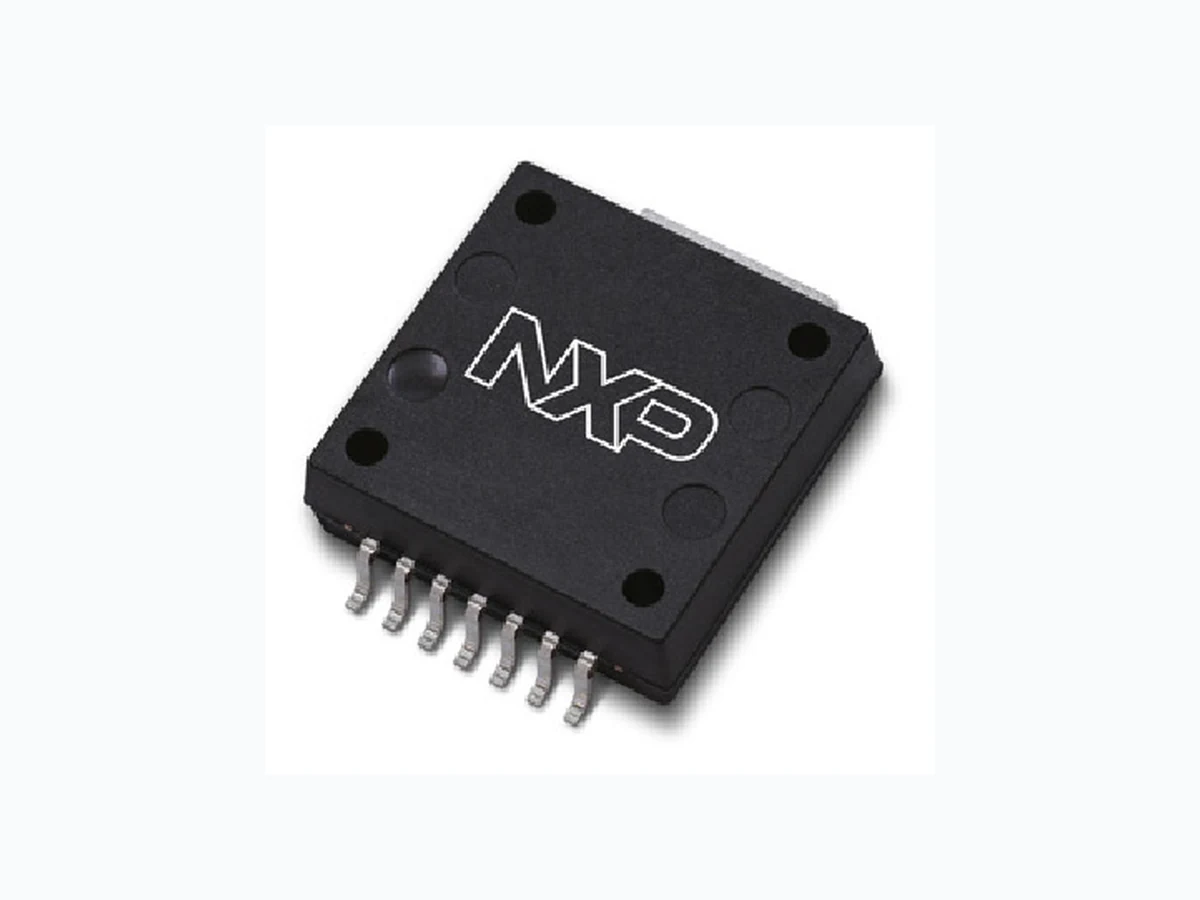
The A3I20X050N integrated Doherty circuit is designed with on--chip matching that makes it usable from 1800 to 2200 MHz. This multi--stage structure is rated for 20 to 32 V operation and covers all typical cellular base
station modulation formats.
1800 MHz Typical Doherty Single--Carrier W--CDMA Characterization Performance: VDD = 28 Vdc, IDQ(Carrier) = 160 mA, VGS(Peaking) = 2.15 Vdc, Pout = 6.3 W Avg.,
Input Signal PAR = 9.9 dB @ 0.01% Probability on CCDF.(1)
| Frequency | Gps (dB) | PAE (%) | ACPR (dBc) |
| 1805 MHz | 28.7 | 38.1 | –37.1 |
| 1840 MHz | 28.7 | 39.1 | –39.7 |
| 1880 MHz | 28.7 | 39.0 | –37.5 |
1800–2200 MHz Typical Doherty Single--Carrier W--CDMA Performance: VDD = 28 Vdc, IDQ(Carrier) = 145 mA, VGS(Peaking) = 2.20 Vdc, Pout = 6.3 W Avg., Input Signal PAR = 9.9 dB @ 0.01% Probability on CCDF.(1)
| Frequency | Gps (dB) | PAE (%) | ACPR (dBc) |
| 1800 MHz | 28.3 | 37.3 | –33.5 |
| 1900 MHz | 28.4 | 38.0 | –37.7 |
| 2000 MHz | 28.7 | 37.6 | –40.9 |
| 2100 MHz | 29.0 | 38.0 | –39.1 |
| 2200 MHz | 29.0 | 37.6 | –34.1 |
- All data measured in fixture with device soldered to heatsink.
Features
Integrated Doherty splitter and combiner On--chip matching (50 ohm input, DC blocked) Integrated quiescent current temperature compensation with enable/disable function (2)
- Refer to AN1977, Quiescent Current Thermal Tracking Circuit in the RF Integrated Circuit Family, and to AN1987, Quiescent Current Control for the RF Integrated Circuit Device Family. Go to http://www.nxp.com/RF and search for AN1977 or AN1987.

Page 2
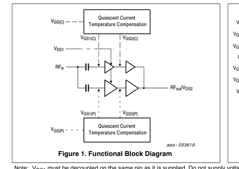
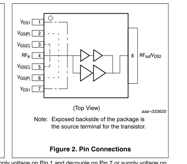
Note: VDS1 must be decoupled on the same pin as it is supplied. Do not supply voltage on Pin 1 and decouple on Pin 7 or supply voltage on Pin 7 and decouple on Pin 1. Maximum current allowed between Pin 1 and Pin 7 inside the device is 1.8 A.
Table 1. Maximum Ratings
| Rating | Symbol | Value | Unit |
|---|---|---|---|
| Drain--Source Voltage | VDSS | –0.5, +65 | Vdc |
| Gate--Source Voltage | VGS | –0.5, +10 | Vdc |
| Operating Voltage | VDD | 32, +0 | Vdc |
| Storage Temperature Range | Tstg | –65 to +150 | C |
| Case Operating Temperature Range | TC | –40 to +150 | C |
| Operating Junction Temperature Range (1,2) | TJ | –40 to +225 | C |
| Input Power | Pin | 20 | dBm |
Table 2. Thermal Characteristics

Table 3. ESD Protection Characteristics
| Test Methodology | Class |
| Human Body Model (per JS--001--2017) | Class 2 |
| Charge Device Model (per JS--002--2014) | Class C2b |
Table 4. Moisture Sensitivity Level
| Test Methodology | Rating | Package Peak Temperature | Unit |
|---|---|---|---|
| Per JESD22--A113, IPC/JEDEC J--STD--020 | 3 | 260 | C |
- Continuous use at maximum temperature will affect MTTF. 2. MTTF calculator available at http://www.nxp.com. 3. Refer to AN1955, Thermal Measurement Methodology of RF Power Amplifiers. Go to http://www.nxp.com/RF and search for AN1955.
Page 3
Table 5. Electrical Characteristics (TA = 25C unless otherwise noted)
Characteristic
Symbol
Min Typ Max Unit
Carrier Stage 1 and Stage 2 — Off Characteristics
| Zero Gate Voltage Drain Leakage Current (VDS1 = VDS2 = 65 Vdc, VGS = 0 Vdc) | IDSS(1+2) | — | — | 10 | Adc |
| Zero Gate Voltage Drain Leakage Current (VDS1 = VDS2 = 32 Vdc, VGS = 0 Vdc) | IDSS(1+2) | — | — | 1 | nAdc |
Carrier Stage 1 and Stage 2 — On Characteristics
| Gate Threshold Voltage (VDS = 10 Vdc, ID = 21 Adc) | VGSC(th) | 0.7 | 1.7 | 2.4 | Vdc |
| Gate Quiescent Voltage (VDS = 28 Vdc, IDQ(Carrier) = 160 mAdc) | VGSC(Q) | — | 2.05 | — | Vdc |
| Fixture Gate Quiescent Voltage (VDD = 28 Vdc, IDQ(Carrier) = 160 mAdc, Measured in Functional Test) | VGGC(Q) | 4.8 | 5.1 | 5.5 | Vdc |
Peaking Stage 1 and Stage 2 — Off Characteristics
| Zero Gate Voltage Drain Leakage Current (VDS1 = VDS2 = 65 Vdc, VGS = 0 Vdc) | IDSS(1+2) | — | — | 10 | Adc |
| Zero Gate Voltage Drain Leakage Current (VDS1 = VDS2 = 32 Vdc, VGS = 0 Vdc) | IDSS(1+2) | — | — | 1 | nAdc |
Peaking Stage 1 and Stage 2 — On Characteristics
| Gate Threshold Voltage (VDS1 = VDS2 = 10 Vdc, ID = 36 Adc) | VGSP(th) | 0.7 | 1.7 | 2.4 | Vdc |
| Drain--Source On--Voltage (VGS2(Peaking) = 10 Vdc, ID = 360 mAdc) Stage 2 | VDS(on) | 0.05 | 0.2 | 0.3 | Vdc |
(continued)
Page 4
Table 5. Electrical Characteristics (TA = 25C unless otherwise noted) (continued)
Characteristic
Symbol
Min Typ Max Unit
Functional Tests (1,2) (In NXP Production Test Fixture, 50 ohm system) VDD = 28 Vdc, IDQ(Carrier) = 160 mA, VGS(Peaking) = 2.15 Vdc, Pout = 6.3 W Avg., f = 1840 MHz, Single--Carrier W--CDMA, IQ Magnitude Clipping, Input Signal PAR = 9.9 dB @ 0.01% Probability on CCDF. ACPR measured in 3.84 MHz Channel Bandwidth @ 5 MHz Offset.
| Power Gain | Gps | 28.0 | 29.3 | 31.0 | dB |
| Power Added Efficiency | PAE | 36.7 | 39.5 | — | % |
| Adjacent Channel Power Ratio | ACPR | — | –37.2 | –33.0 | dBc |
| Pout @ 3 dB Compression Point, CW | P3dB | 57.5 | 63.1 | — | W |
Wideband Ruggedness (In NXP Doherty Production Test Fixture, 50 ohm system) IDQ(Carrier) = 160 mA, VGS(Peaking) = 2.15 Vdc, f = 1840 MHz, Additive White Gaussian Noise (AWGN) with 10 dB PAR
| ISBW < 120 MHz | No Device Degradation |
| ISBW > 120 MHz | Maintain Pout at < 10 dB OBO and VDD at < 30 V |
Typical Performance (3) (In NXP Characterization Test Fixture, 50 ohm system) VDD = 28 Vdc, IDQ(Carrier) = 160 mA, VGS(Peaking) = 2.15 Vdc, 1805–1880 MHz Bandwidth
| Pout @ 3 dB Compression Point (4) | P3dB | — | 63.0 | — | W |
| AM/PM (Maximum value measured at the P3dB compression point across the 1805–1880 MHz frequency range.) | | — | –19 | — | |
| VBW Resonance Point (IMD Third Order Intermodulation Inflection Point) | VBWres | — | 190 | — | MHz |
| Quiescent Current Accuracy over Temperature (5) with 2 kGate Feed Resistors (–30 to 85C) Stage 1+2 (Carrier) | IQT | — | 6.5 | — | % |
| Gain Flatness in 75 MHz Bandwidth @ Pout = 6.3 W Avg. | GF | — | 0.3 | — | dB |
| Gain Variation over Temperature (–40C to +85C) | G | — | 0.037 | — | dB/C |
| Output Power Variation over Temperature (–40C to +85C) | P3dB | — | 0.009 | — | dB/C |
Table 6. Ordering Information
| Device | Tape and Reel Information | Package |
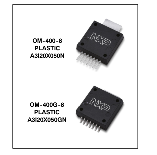
| A3I20X050NR1 | R1 Suffix = 500 Units, 32 mm Tape Width, 13--inch Reel | OM--400--8 |
| A3I20X050GNR1 | OM--400G--8 |
- Part internally input and output matched. 2. Measurements made with device in straight lead configuration before any lead forming operation is applied. Lead forming is used for gull wing (GN) parts. 3. All data measured in fixture with device soldered to heatsink. 4. P3dB = Pavg + 7.0 dB where Pavg is the average output power measured using an unclipped W--CDMA single--carrier input signal where output PAR is compressed to 7.0 dB @ 0.01% probability on CCDF. 5. Refer to AN1977, Quiescent Current Thermal Tracking Circuit in the RF Integrated Circuit Family, and to AN1987, Quiescent Current Control for the RF Integrated Circuit Device Family. Go to http://www.nxp.com/RF and search for AN1977 or AN1987.
Page 5
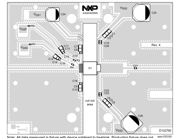
Note: All data measured in fixture with device soldered to heatsink. Production fixture does not include device soldered to heatsink.
Figure 3. A3I20X050N Characterization Test Circuit Component Layout — 1805–1880 MHz
Table 7. A3I20X050N Characterization Test Circuit Component Designations and Values — 1805–1880 MHz
| Part | Description | Part Number | Manufacturer |
|---|---|---|---|
| C1, C2, C3, C4, C5, C6, C7, C8, C9, C10, C11, C12 | 10 F Chip Capacitor | C3225X7S1H106M250AB | TDK |
| C13, C14 | 10 nF Chip Capacitor | C0805C103K5RAC | Kemet |
| C15, C16, C17, C18, C19, C20, C21, C22, C23 | 10 pF Chip Capacitor | 600S100JT250XT | ATC |
| C24 | 150 F, 100 V Electrolytic Capacitor | EEVFK2A151M | Panasonic |
| C25, 26 | 220 F, 100 V Electrolytic Capacitor | EEVFK2A221M | Panasonic |
| Q1 | RF Power LDMOS Amplifier | A3I20X050N | NXP |
| R1, R2 | 2.2 k, 1/8 W Chip Resistor | CRCW08052K20JNEA | Vishay |
| R3, R4 | 10 , 1/8 W Chip Resistor | CRCW080510R0FKEA | Vishay |
| PCB | Rogers RO4350B, 0.020, r = 3.66 | D122782 | MTL |
Page 6
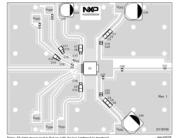
Note: All data measured in fixture with device soldered to heatsink.
Figure 4. A3I20X050GN Test Circuit Component Layout — 1800–2200 MHz
Table 8. A3I20X050GN Test Circuit Component Designations and Values — 1800–2200 MHz
| Part | Description | Part Number | Manufacturer |
|---|---|---|---|
| C1, C2, C3, C4, C5, C6, C7, C8, C9, C10, C11, C12 | 10 F Chip Capacitor | C3225X7S1H106M250AB | TDK |
| C13, C14 | 10 nF Chip Capacitor | C0805C103K5RAC | Kemet |
| C15, C16, C17, C18, C19, C20, C21, C22, C23 | 10 pF Chip Capacitor | 600S100JT250XT | ATC |
| C24 | 150 F, 100 V Electrolytic Capacitor | EEVFK2A151M | Panasonic |
| C25, 26 | 220 F, 100 V Electrolytic Capacitor | EEVFK2A221M | Panasonic |
| C27 | 0.8 pF Chip Capacitor | 06035J0R8BBS | AVX |
| C28 | 1.8 pF Chip Capacitor | 600S1R8BT250XT | ATC |
| Q1 | RF Power LDMOS Amplifier | A3I20X050GN | NXP |
| R1, R2 | 2.2 k, 1/8 W Chip Resistor | CRCW08052K20JNEA | Vishay |
| R3, R4 | 10 , 1/8 W Chip Resistor | CRCW080510R0FKEA | Vishay |
| PCB | Rogers RO4350B, 0.020, r = 3.66 | D116745 | MTL |
Page 7
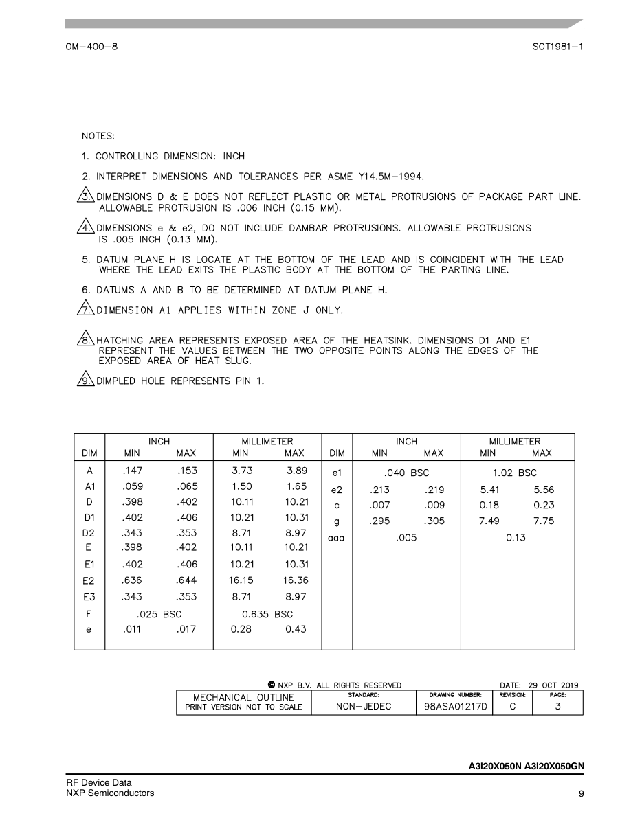
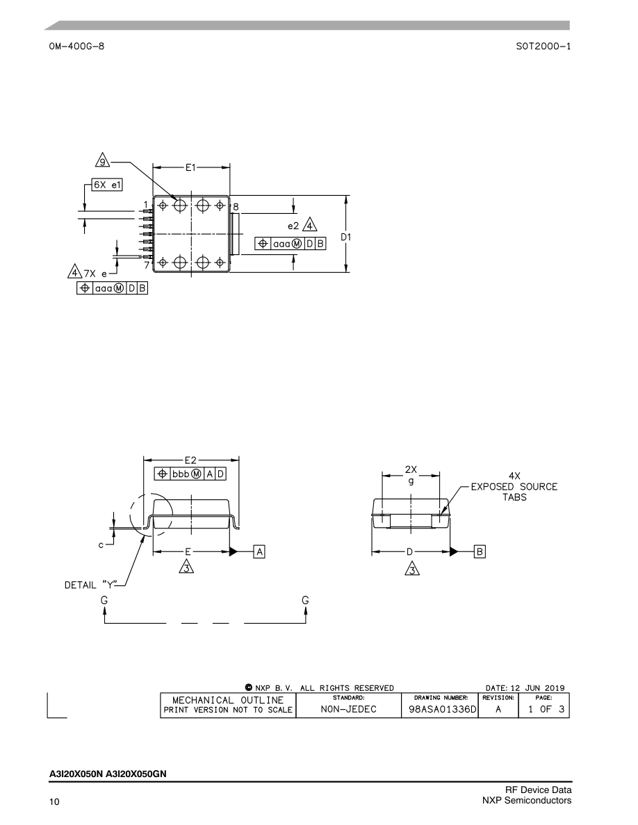
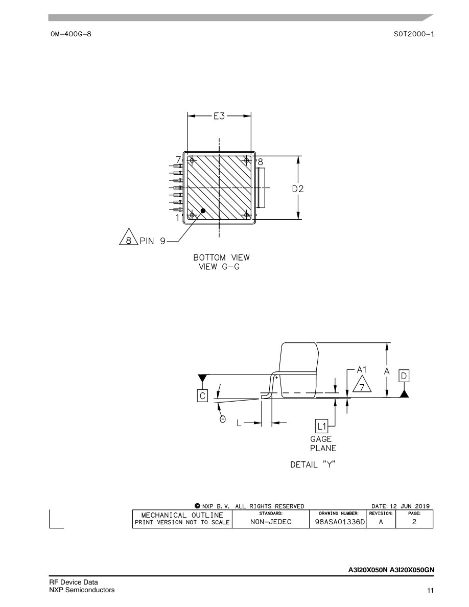
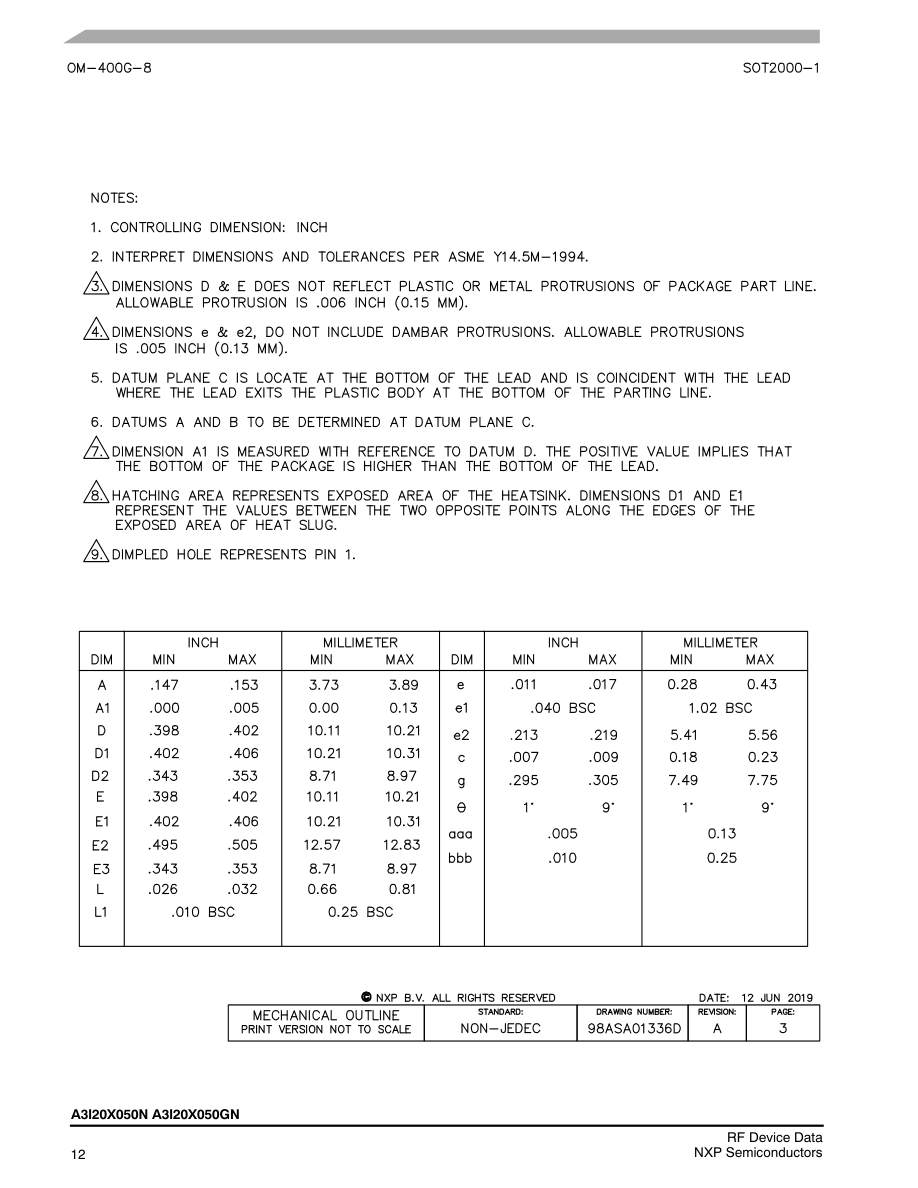
PACKAGE INFORMATION
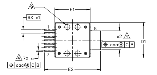
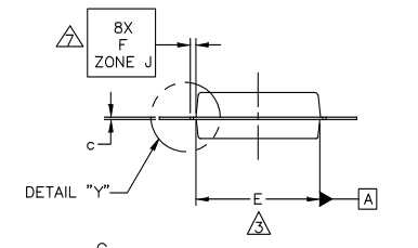
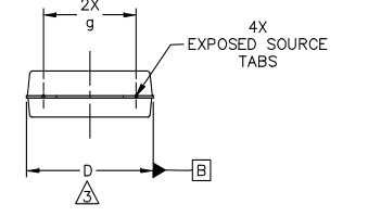
Page 8
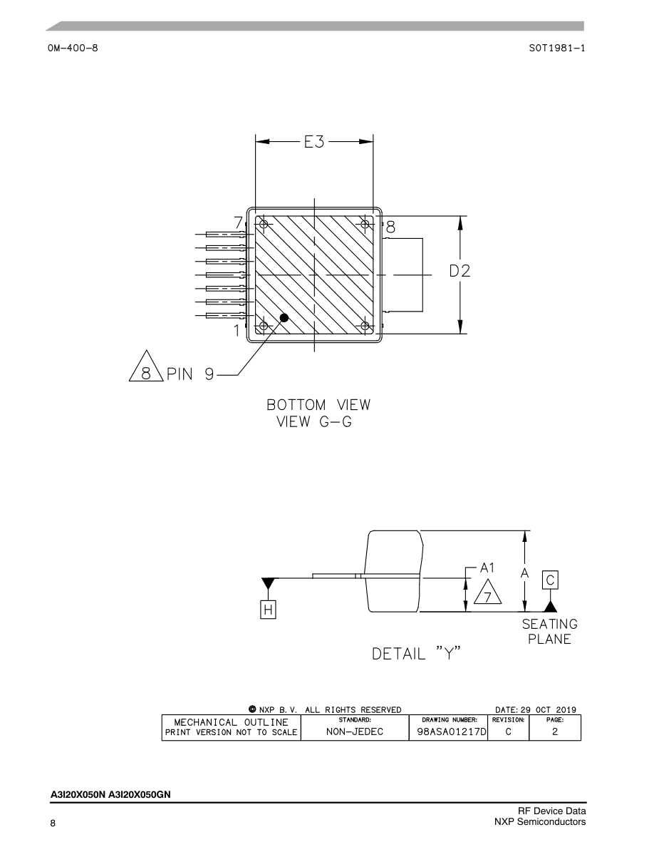
Page 9
Page 10
Page 11
Page 12
Page 13
PRODUCT DOCUMENTATION, SOFTWARE AND TOOLS
Refer to the following resources to aid your design process. Application Notes AN1907: Solder Reflow Attach Method for High Power RF Devices in Plastic Packages AN1955: Thermal Measurement Methodology of RF Power Amplifiers AN1977: Quiescent Current Thermal Tracking Circuit in the RF Integrated Circuit Family AN1987: Quiescent Current Control for the RF Integrated Circuit Device Family Engineering Bulletins EB212: Using Data Sheet Impedances for RF LDMOS Devices Software Electromigration MTTF Calculator RF High Power Model .s2p File Development Tools Printed Circuit Boards
REVISION HISTORY
The following table summarizes revisions to this document.
| Revision | Date | Description |
|---|---|---|
| 0 | Oct. 2019 | Initial release of data sheet |
| 1 | Dec. 2019 | Table 6, Ordering Information: changed tape and reel suffix to R1 to reflect orderable quantity of 500 units, p. 4 Package Outline Drawing: OM--400--8 package outline updated to Rev. C, pp. 7–9 |
| 2 | May 2020 | Wideband Ruggedness table: Ruggedness results were changed based on ISBW. ISBW was split at 120MHz to differentiate ISBW performance between varying applications, p. 4 |
Page 14
Information in this document is provided solely to enable system and software
How to Reach Us:
implementers to use NXP products. There are no express or implied copyright licenses granted hereunder to design or fabricate any integrated circuits based on the information
Home Page:
in this document. NXP reserves the right to make changes without further notice to any
nxp.com
products herein.
Web Support:
NXP makes no warranty, representation, or guarantee regarding the suitability of its
nxp.com/support
products for any particular purpose, nor does NXP assume any liability arising out of the application or use of any product or circuit, and specifically disclaims any and all liability, including without limitation consequential or incidental damages. “Typical” parameters that may be provided in NXP data sheets and/or specifications can and do vary in different applications, and actual performance may vary over time. All operating parameters, including “typicals,” must be validated for each customer application by customer’s technical experts. NXP does not convey any license under its patent rights nor the rights of others. NXP sells products pursuant to standard terms and conditions of
sale, which can be found at the following address: nxp.com/SalesTermsandConditions.
NXP, the NXP logo and Airfast are trademarks of NXP B.V. All other product or service names are the property of their respective owners. E 2019–2020 NXP B.V.
