

 Download PDF
T92_V01 TEC
Document overview
- Manufacturer or author: Provided By digicamel.com
- PDF pages: 5
Technical content
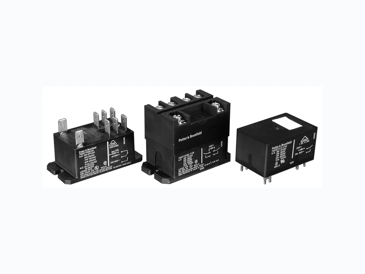
04-2021, Rev. 0421 www.te.com © 2012 Tyco Electronics Corporation, a TE Connectivity Ltd. company. Catalog and product specification according to IEC 61810-1 and to be used only together with the ‘Definitions’ section. Catalog and product data is subject to the terms of the disclaimer and all chapters of the ‘Definitions’ section, available at http://relays.te.com/definitions Catalog product data, ‘Definitions’ section, application notes and all specifications are subject to change. Potter & Brumfield General Purpose High Power PCB Relays T92 Series Two-pole Power Relay (Continued) Potter & Brumfield Insulation Data Initial dielectric strength between open contacts 1500Vrms between contact and coil 4000Vrms between adjacent contact 2000Vrms Initial surge withstand voltage between contact and coil 8kV Initial insulation resistance (@500VDC) between insulated elements 1x10⁹Ω Clearance/creepage between contact and coil 8mm clearance/9.5mm creepage Other Data Material compliance: EU RoHS/ELV, China RoHS, REACH, Halogen content refer to the Product Compliance Support Center at www.te.com/customersupport/rohssupportcenter Ambient temperature DC coil -55ºC to 85ºC AC coil -55ºC to 65ºC Category of environmental protection IEC 61810 RTI - dust protected, RTII - flux proof, RTIII - wash tight Vibration resistance (functional) 1.65mm max amplitude, 10-55 Hz Shock resistance (functional) 10G for 11msec Shock resistance (destructive) 100G Terminal type PCB / Quick Connect / Screw Coil Data (continued) 120 100 90 95 100 105 110 115 120 125 130 135 140 145 150 Applied Coil Voltage (% of Rated Nominal) Max. Allowable Ambient Temp. (°C) DC Coil 0 Amp Contact Load 70 75 80 85 DC Coil 30 Amp Contact Load AC Coil 30 A AC Coil 0 A Coil Data Coil voltage range 5 to 110VDC; 12 to 240VAC Max. coil power 1.7W; 4.0VA Max. coil temperature 155°C Coil insulation system according UL Class F Coil versions, DC coil (D type) Coil Rated Operate Release Coil Rated coil code voltage2) voltage 3) voltage resistance power VDC VDC VDC Ω±10% W 5 5 3.75 0.6 14.9 6 6 4.5 0.6 22 9 9 6.75 0.9 48 12 12 9 1.2 86 18 18 13.5 1.8 197 1.7W/ 22 22 16.5 2.2 294 Min. 0.41W 24 24 18 2.4 350 hold 36 36 27 3.6 767 48 48 36 4.8 1390 110 110 82.5 11 7255 120 120 90 12 8514 2) For T92H type, after the energization time of 100ms with rated voltage, the coil requires a reduction of the coil voltage to 50% of rated voltage. 3) For Anti-explosion sealed type, the operate voltage is 80% of the rated coil voltage. Coil versions, AC coil (A type) Coil Rated Frequency Operate Release Coil Rated coil code voltage voltage voltage resistance power VAC Hz VAC, 60Hz VAC, 60Hz Ω±10% VA 12 12 60 9.6 1.2 9.1 4 24 24 60 19.2 2.4 36.6 4 110 110 60 88 11 793 4 120 110/120 50/60 96 12 950 4 208 208 60 166.4 20.8 2841 4 240 220/240 50/60 192 24 3800 4 277 250/277 50/60 221.6 27.7 5485 4 Coil versions, AC coil (F type) Coil Rated Frequency Operate Release Coil Rated coil code voltage voltage voltage resistance power VAC Hz VAC, 60Hz VAC, 60Hz Ω±10% VA 12 12 50 9.6 1.2 11.2 3.5 24 24 50 19.2 2.4 44.4 3.5 48 48 50 38.4 4.8 179.2 3.5 240 240 50 192 24 4355 3.5 All figures are given for coil without preenergization, at ambient temperature +23°C. For A type, 110V/120V, 50/60Hz. Signify 50Hz Operation at Nominal 110V, 60 Hz Operation at Nominal 120V. Note: This chart only apply for T92 standard type. For coil data of T92 Anti- explosion sealed type and T92H type, please contact TE engineering.
04-2021, Rev. 0421 www.te.com © 2012 Tyco Electronics Corporation, a TE Connectivity Ltd. company. Catalog and product specification according to IEC 61810-1 and to be used only together with the ‘Definitions’ section. Catalog and product data is subject to the terms of the disclaimer and all chapters of the ‘Definitions’ section, available at http://relays.te.com/definitions Catalog product data, ‘Definitions’ section, application notes and all specifications are subject to change. Potter & Brumfield General Purpose High Power PCB Relays T92 Series Two-pole Power Relay (Continued) Potter & Brumfield Terminal assignment Bottom view on pins 2 form A 2 form C T92 – Mounting and termination code 5 PCB layout Bottom view on pins T92/T92H - Mounting and termination code 1 An alternate PC board layout utilizes .076 ± .003 (1.93 ± .076) diameter holes on the same center-to-center spacing shown above. Use of the rectangular holes is recommended for improved solderability. Only necessary terminals are present on single throw models. Consequently, some holes will be unnecessary for single throw models. 2.700 MAX. (68.58) 2.135 MAX. (54.23) 2.345 ± .005 (59.56 ± .13) .913 MAX. (23.19) 2.010 MAX. (51.05) 1.431 MAX. (36.34) 1.36 MAX. (34.54) .090 (2.29) RAD. FOR #8 SCREW 1.618 (41.10).585 (14.86).309 (7.85) .630 (16.00) .203 TYP. (5.16) .052 TYP. (1.32) .072 TYP. (1.83) 1.000 (25.40) .162 (4.12) .365 (9.27) .185 (4.70) Dimensions T92/T92H – Mounting and termination code 1 2.06 MAX. (52.32) 1.618 ± .020 (7.85 ± .13) 1.36 MAX. (34.54) 1.21 MAX. (30.73) .630 ± .005 (16.00 ± .13) .156 ± 0.012 (3.96 ± 0.3) .250 TYP. (6.35) 1.000 ± .010 (25.40 ± .25) .032 TYP. (0.81) .047 TYP. (1.19) Pre-soldering in below side T92 – Mounting and termination code 2, 3 and 4 2.700 MAX. (68.58) 2.05 MAX. (52.07) 1.618 TYP. (7.85 ± .13) 1.36 MAX. (34.54) 1.04 MAX. (26.42) .630 TYP. (16.00) 2.345 ± .005 (59.56 ± .13) .090 RAD. (2.29) FOR #8 SCREW 1.495 MAX. (37.97) Note: Dimensions of the pins after tin soldering a) +0.3mm for the width and the thickness b) +1.0mm for the length
04-2021, Rev. 0421 www.te.com © 2012 Tyco Electronics Corporation, a TE Connectivity Ltd. company. Catalog and product specification according to IEC 61810-1 and to be used only together with the ‘Definitions’ section. Catalog and product data is subject to the terms of the disclaimer and all chapters of the ‘Definitions’ section, available at http://relays.te.com/definitions Catalog product data, ‘Definitions’ section, application notes and all specifications are subject to change. Potter & Brumfield T92 Series Two-pole Power Relay (Continued) Product code structure (T92H type) Typical product code T92H P 7 D 1 X -12 Type T92H Power relay T92 High Performance (50A) Enclosure P Dust protected plastic case S Wash-tight, tape sealed, plastic case (Mounting and termination code 1) Contact arrangement 7 2 form A (2 NO) Coil Input D DC voltage Mounting and termination 1 Printed circuit board mount; printed circuit board terminals. Contact material X Special Ag Alloy X (Cd Free) Coil voltage Coil code: please refer to coil versions table Product code Enclosure Contacts Coil Mounting Contact Material Coil Part number T92HP7D1X-12 Plastic dust cover 2 form A, 2 NO DC PCB terminals Special Ag Alloy X (Cd Free) 12VDC 6-1423008-6 T92HP7D1X-24 24VDC 6-1423008-7 T92HP7D1X-48 48VDC 6-1423008-9 Product code structure Typical product code T92 S 11 D 2 2 -24 -99 Type T92 Printed circuit board / panel mount power relay T92 Enclosure P Dust protected plastic case S Wash-tight, tape sealed, plastic case (Mounting and termination code 1) Wash-tight, glue sealed, plastic case (Mounting and termination code 1, 2 for anti-explosion version) Top sealed, not wash-tight, not tape sealed on bottom (Mounting and termination codes 2, 3 & 4) Contact arrangement 7 2 form A (2 NO) 11 2 form C (2 CO) Coil Input A AC voltage, 60Hz or 50/60 Hz (consult coil versions table) D DC voltage F AC voltage, 50Hz Mounting and termination 1 Printed circuit board mount; printed circuit board terminals. 2 Panel mount via flanged cover; .250” (6.35mm) x .032” (.81mm) QC terminal 5 Panel mount via flanged cover, M4 screws w/ captive pressure plates. Requires Enclosure P and Contact arrangement 7. Contact material
2 AgCdO 4 AgSnOInO X Special Ag Alloy X (Cd Free)
Coil code: please refer to coil versions table Customer code -99 Anti-explosion -00 WG version Note. This list represents the most common types and does not show all variants covered by this datasheet, other types on request. Product code structure (T92 type)
04-2021, Rev. 0421 www.te.com © 2012 Tyco Electronics Corporation, a TE Connectivity Ltd. company. Catalog and product specification according to IEC 61810-1 and to be used only together with the ‘Definitions’ section. Catalog and product data is subject to the terms of the disclaimer and all chapters of the ‘Definitions’ section, available at http://relays.te.com/definitions Catalog product data, ‘Definitions’ section, application notes and all specifications are subject to change. Potter & Brumfield General Purpose High Power PCB Relays T92 Series Two-pole Power Relay (Continued) Potter & Brumfield Product Code Enclosure Contacts Coil Mounting Contact Material Coil Part Number T92P7A22-24 Plastic dust cover 2 form A, 2 NO AC Panel mount + quick connect AgCdO 24 VAC 6-1393211-0 T92P7A22-120 120 VAC 5-1393211-7 T92P7A22-240 240 VAC 6-1393211-2 T92P7A22-277 277 VAC 6-1393211-3 T92P7A24-240 AgSnOInO 240 VAC 3-1423008-3 T92P7A52-120 Panel mount + screw terminals AgCdO 120 VAC 1423008-8 T92P7A52-240 240 VAC 1-1423008-2 T92P7D12-12 DC PCB terminals 12 VDC 6-1393211-5 T92P7D14-12 AgSnOInO 12 VDC 2-1423008-1 T92P7D12-24 AgCdO 24 VDC 6-1393211-6 T92P7D22-12 Panel mount + quick connect 12VDC 6-1393211-9 T92P7D22-24 24 VDC 7-1393211-1 T92P7D22-48 48 VDC 7-1393211-2 T92P7D24-12 AgSnOInO 12VDC 2-1423008-2 T92P7D24-24 24 VDC 1423008-9 T92P7D42-24 AgCdO 7-1393211-5 T92P7D52-12 Panel mount + screw terminals 12 VDC 1-1423008-0 T92P7D52-24 24 VDC 1423967-1 T92P11A12-120 2 form C, 2 CO AC PCB terminals 120 VAC 3-1393211-8 T92P11A22-12 Panel mount + quick connect 12 VAC 3-1393211-9 T92P11A22-24 24 VAC 4-1393211-3 T92P11A22-120 120 VAC 4-1393211-0 T92P11A22-240 240 VAC 4-1393211-4 T92P11A22-277 277 VAC 4-1393211-6 T92P11A24-240 AgSnOInO 240 VAC 3-1423008-7 T92P11A42-120 AgCdO 120VAC 4-1393211-8 T92P11D12-12 DC PCB terminals 12 VDC 5-1393211-0 T92P11D22-12 Panel mount + quick connect 5-1393211-3 T92P11D22-24 24 VDC 5-1393211-4 T92P11D24-12 AgSnOInO 12 VDC 3-1423008-5 T92P11D24-24 24 VDC 3-1423008-6 T92S7A12-24 Wash tight 2 form A, 2 NO AC PCB terminals AgCdO 24 VAC 9-1393211-8 T92S7A12-120 120 VAC 9-1393211-7 T92S7A12-240 240 VAC 9-1393211-9 T92S7A22-24 Top sealed Panel mount + quick connect 24 VAC 1393212-4 T92S7A22-120 120 VAC 1393212-2 T92S7A22-240 240 VAC 1393212-5 T92S7D12-12 Wash tight DC PCB terminals 12 VDC 1393212-8 T92S7D12-24 24 VDC 1-1393212-0 T92S7D12-48 48 VDC 1-1393212-1 T92S7D12-110 110 VDC 1393212-7 T92S7D14-12 AgSnOInO 12 VDC 1-1423008-6 T92S7D14-24 24 VDC 1-1423008-8 T92S7D22-12 Top sealed Panel mount + quick connect AgCdO 12 VDC 1-1393212-4 T92S7D22-18 18 VDC 1-1393212-5 T92S7D22-24 24 VDC 1-1393212-7 T92S7D22-110 110 VDC 1-1393212-3 T92S11A12-24 Wash tight 2 form C, 2 CO AC PCB terminals 24 VAC 8-1393211-1 T92S11A12-120 120 VAC 8-1393211-0 T92S11A12-240 240 VAC 8-1393211-2 T92S11A22-12 Top sealed Panel mount + quick connect 12 VAC 8-1393211-3 T92S11A22-24 24 VAC 8-1393211-6 T92S11A22-120 120 VAC 8-1393211-4 T92S11A22-240 240 VAC 8-1393211-7 T92S11D12-12 Wash tight DC PCB terminals 12 VDC 8-1393211-9 T92S11D12-24 24 VDC 9-1393211-0 T92S11D12-48 48 VDC 9-1393211-1 T92S11D12-110 110 VDC 8-1393211-8 T92S11D22-12 Top sealed Panel mount + quick connect 12 VDC 9-1393211-3 T92S11D22-24 24 VDC 9-1393211-4 T92P7D12-12-99 Plastic dust cover 2 form A, 2 NO DC PCB terminals AgCdO 12VDC 2-2071223-3 T92S7D1X-12-99 Wash tight Special Ag Alloy 12VDC 6-1423008-1 T92S7D2X-12-99 Panel mount + quick connect X (Cd Free) 12VDC 6-1423008-2 T92S7A22-240-00 Top Sealed(WG) AC AgCdO 240VAC 2-2071223-4 T92S7D12-12-00 Wash tight (WG) DC PCB terminals 12VDC 1-2071223-7 Note. This list represents the most common types and does not show all variants covered by this datasheet, other types on request.