
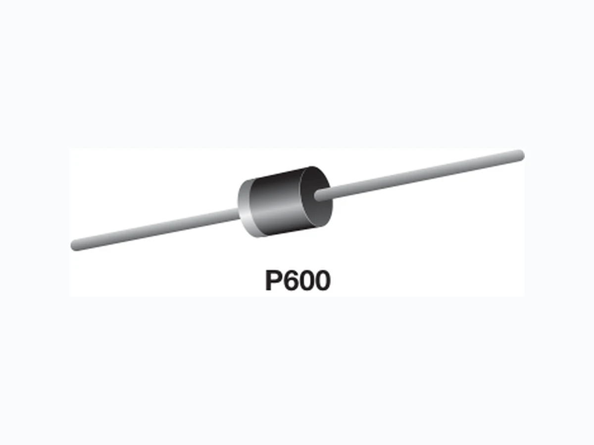
5KP24A-E3 VISHAY
Document overview
- Manufacturer or author: Provided By digicamel.com
- PDF pages: 5
Technical content
5KP5.0A thru 5KP188A www.vishay.com Vishay General Semiconductor Revision: 20-Nov-12 1 Document Number: 88308 For technical questions within your region: DiodesAmericas@vishay.com, DiodesAsia@vishay.com, DiodesEurope@vishay.com THIS DOCUMENT IS SUBJECT TO CHANGE WITHOUT NOTICE. THE PRODUCTS DESCRIBED HEREIN AND THIS DOCUMENT ARE SUBJECT TO SPECIFIC DISCLAIMERS, SET FORTH AT www.vishay.com/doc?91000 TRANSZORB® Transient Voltage Suppressors
FEATURES
- P600 glass passivated chip junction
- Available in uni-directional polarity only
- 5000 W peak pulse power capability with a 10/1000 μs waveform, repetitive rate (duty cycle): 0.01 %
- Excellent clamping capability
- Very fast response time
- Low incremental surge resistance
- Solder dip 275 °C max. 10 s, per JESD 22-B106
- AEC-Q101 qualified
- Material categorization: For definitions of compliance please see www.vishay.com/doc?99912 TYPICAL APPLICATIONS Use in sensitive electronics protection against voltage transients induced by inductive load switching and lighting on ICs, MOSFET, signal lines of sensor units for consumer, computer, industrial, automotive, and telecommunication. MECHANICAL DATA Case: Molded epoxy body over passivated junction Molding compound meets UL 94 V-0 flammability rating Base P/N-E3 - RoHS compliant, commercial grade Base P/NHE3 - RoHS compliant, AEC-Q101 qualified Terminals: Matte tin plated leads, solderable per J-STD-002 and JESD 22-B102 E3 suffix meets JESD 201 class 1A whisker test, HE3 suffix meets JESD 201 class 2 whisker test Polarity: Color band denotes cathode end Notes (1) Non-repetitive current pulse, per fig. 3 and derated above TA = 25 °C per fig. 2 (2) Measured 8.3 ms single half sine-wave or equivalent square wave, duty cycle = 4 pulses per minute maximum PRIMARY CHARACTERISTICS VWM 5.0 V to 188 V VBR 6.4 V to 231 V PPPM 5000 W PD 8.0 W IFSM 500 A TJ max. 175 °C Polarity Uni-directional Package P600 P600 MAXIMUM RATINGS (TA = 25 °C unless otherwise noted) PARAMETER SYMBOL LIMIT UNIT Peak pulse power dissipation with a 10/1000 μs waveform (1) P PPM 5000 W Peak pulse current with a 10/1000 μs waveform (1) I PPM See next table A Power dissipation on infinite heatsink at TL = 75 °C (fig. 5) P D 8.0 W Peak forward surge current 8.3 ms single half sine-wave (fig. 5) I FSM 600 A Instantaneous forward voltage at 100 A (2) VF 3.5 V Operating junction and storage temperature range T J, TSTG - 55 to + 175 °C
5KP5.0A thru 5KP188A www.vishay.com Vishay General Semiconductor Revision: 20-Nov-12 2 Document Number: 88308 For technical questions within your region: DiodesAmericas@vishay.com, DiodesAsia@vishay.com, DiodesEurope@vishay.com THIS DOCUMENT IS SUBJECT TO CHANGE WITHOUT NOTICE. THE PRODUCTS DESCRIBED HEREIN AND THIS DOCUMENT ARE SUBJECT TO SPECIFIC DISCLAIMERS, SET FORTH AT www.vishay.com/doc?91000 Notes (1) Pulse test: tp 50 ms (2) Surge current waveform per fig. 3 and derate per fig. 2 (3) All terms and symbols are consistent with ANSI/IEEE CA62.35 ELECTRICAL CHARACTERISTICS (JEDEC REGISTERED DATA) (TA = 25 °C unless otherwise noted) DEVICE TYPE BREAKDOWN VOLTAGE V BR AT IT (1) (V) TEST CURRENT IT (mA) STAND-OFF VOLTAGE VWM (V) MAXIMUM REVERSE LEAKAGE AT VWM ID (μA) MAXIMUM PEAK PULSE CURRENT IPPM (2) (A) MAXIMUM CLAMPING VOLTAGE AT IPPM VC (V) MAXIMUM TEMP. COEFFICIENT OF VBR (%/°C)MIN. MAX. 5KP100A 111 123 5.0 100 2.0 30.9 162 0.110 5KP110A 122 135 5.0 110 2.0 28.2 177 0.112 5KP120A 133 147 5.0 120 2.0 25.9 193 0.112 5KP130A 144 159 5.0 130 2.0 23.9 209 0.112 5KP150A 167 185 5.0 150 2.0 20.6 243 0.112 5KP160A 178 197 5.0 160 2.0 19.3 259 0.112 5KP170A 189 209 5.0 170 2.0 18.2 275 0.112 5KP188A 209 231 5.0 188 2.0 15.2 328 0.112
5KP5.0A thru 5KP188A www.vishay.com Vishay General Semiconductor Revision: 20-Nov-12 3 Document Number: 88308 For technical questions within your region: DiodesAmericas@vishay.com, DiodesAsia@vishay.com, DiodesEurope@vishay.com THIS DOCUMENT IS SUBJECT TO CHANGE WITHOUT NOTICE. THE PRODUCTS DESCRIBED HEREIN AND THIS DOCUMENT ARE SUBJECT TO SPECIFIC DISCLAIMERS, SET FORTH AT www.vishay.com/doc?91000 Note (1) AEC-Q101 qualified RATINGS AND CHARACTERISTICS CURVES (TA = 25 °C unless otherwise noted) Fig. 1 - Peak Pulse Power Rating Curve Fig. 2 - Pulse Power or Current vs. Initial Junction Temperature Fig. 3 - Pulse Waveform Fig. 4 - Typical Junction Capacitance ORDERING INFORMATION (Example) PREFERRED P/N UNIT WEIGHT (g) PREFERRED PACKAGE CODE BASE QUANTITY DELIVERY MODE 5KP5.0A-E3/54 2.776 54 800 13" diameter paper tape and reel 5KP5.0AHE3/54 (1) 2.776 54 800 13" diameter paper tape and reel 0.1 µs 1.0 µs 10 µs 100 µs 1 ms 10 ms 0.1 1.0 100 Non-Repetitive pulse waveform shown in Fig. 3 TA = 25 °C P PPM - Peak P ulse Po wer (k W td - Pulse Width 100 0 25 50 75 100 125 150 175 200 Peak P ulse P ower (P PP ) or C urrent (I PP Derating in Percentage, % TJ - Initial Temperature (°C) 100 150 tr = 10 µs Peak Value IPPM Half Value - IPPM IPP td 10/1000 µs Waveform as defined by R.E.A. 0 1.0 2.0 3.0 4.0 t - Time (ms) IPPM - Peak P ulse Current, % I RSM TJ = 25 °C Pulse Width (td) is defined as the Point where the Peak Current decays to 50 % of I PPM 1 10 100 200 100 1000 10 000 100 000 C J - J unction Capacitance (pF) VWM - Reverse Stand-Off Voltage (V) Measured at Zero Bias Measured at Stand-Off Voltage VWM TJ = 25 °C f = 1.0 MHz V sig = 50 mVp-p
5KP5.0A thru 5KP188A www.vishay.com Vishay General Semiconductor Revision: 20-Nov-12 4 Document Number: 88308 For technical questions within your region: DiodesAmericas@vishay.com, DiodesAsia@vishay.com, DiodesEurope@vishay.com THIS DOCUMENT IS SUBJECT TO CHANGE WITHOUT NOTICE. THE PRODUCTS DESCRIBED HEREIN AND THIS DOCUMENT ARE SUBJECT TO SPECIFIC DISCLAIMERS, SET FORTH AT www.vishay.com/doc?91000 Fig. 5 - Power Derating Curve Fig. 6 - Maximum Non-Repetitive Forward Surge Current PACKAGE OUTLINE DIMENSIONS in inches (millimeters) APPLICATION NOTES The 5KP series of high power transient voltage suppressors were designed to be used on the output of switching power supplies. These devices may be used to replace crowbar circuits. Both the 5 % and 10 % voltage tolerances are referenced to the power supply output voltage level. They are able to withstand high levels of peak current while allowing a circuit breaker to trip or a fuse blow before shorting. This will enable the user to reset the breaker or replace the fuse and continue operation. For this type operation, it is recommended that a sufficient mounting surface be used for dissipatin g the heat generated by the Transient Voltage Suppressor during the transient or over-voltage condition. Lead Lengths P D - Po wer Dissipation ( W TL - Lead Temperature (°C) 60 Hz Resistive or Inductive Load 0 25 50 75 100 125 150 175 200 1 10 100 200 300 400 500 450 350 250 8.3 ms Single Half Sine-Wave Number of Cycles at 60 Hz IFSM - Peak For ward S urge C urrent (A) 0.052 (1.32) 0.048 (1.22) 0.360 (9.1) 0.340 (8.6) DIA. 1.0 (25.4) MIN. 0.360 (9.1) 0.340 (8.6) 1.0 (25.4) MIN. P600
www.vishay.com Vishay Revision: 02-Oct-12 1 Document Number: 91000 Disclaimer ALL PRODUCT, PRODUCT SPECIFICATIONS AND DATA ARE SUBJECT TO CHANGE WITHOUT NOTICE TO IMPROVE RELIABILITY, FUNCTION OR DESIGN OR OTHERWISE. Vishay Intertechnology, Inc., its affiliates, agents, and employee s, and all persons acting on it s or their behalf (collectivel y, “Vishay”), disclaim any and all liability for any errors, inaccuracies or incompleteness contained in any datasheet or in any other disclosure relating to any product. Vishay makes no warranty, repres entation or guarantee regarding the suitabilit y of the products for any particular purpose or the continuing production of any product. To the maximum extent permitted by applicable law, Vishay disclaims (i) any and all liability arising out of the application or use of any product, (ii) any and all liability, including without limitation specia l, consequential or incidental damages, and (iii) any and all i mplied warranties, including warra nties of fitness for particular purpose, non-infringement and merchantability. Statements regarding the suitability of products for certain type s of applications are based on Vishay’s knowledge of typical requirements that are often placed on Vishay products in generic applications. Such statements are not binding statements about the suitability of products for a particular application. It is the customer’s responsib ility to validate that a particu lar product with the properties descri bed in the product specification is suitable fo r use in a particular application. Parameters provided in datasheets and/or specification s may vary in different applications an d performance may vary over time. All operating parameters, including typical pa rameters, must be validated for each customer application by the customer’s technical experts. Product specifications do not expand or otherwise modify Vish ay’s terms and condit ions of purchase, including but not limited to the warranty expressed therein. Except as expressly indicate d in writing, Vishay products are not designed for use in medical, life-saving, or life-sustaining applications or for any other application in which the failure of the Vi shay product could result in personal injury or death. Customers using or selling Vishay products not expressly indicated for use in such applications do so at their own risk. Please contact authorized Vishay personnel to obtain written terms and conditions regarding products designed for such applications. No license, express or implied, by estoppel or otherwise, to any intellectual prope rty rights is granted by this document or by any conduct of Vishay. Product names and markings noted herein may be trademarks of their respective owners. Material Category Policy Vishay Intertechnology, Inc. hereby certi fies that all its products that are id entified as RoHS-Compliant fulfill the definitions and restrictions defined under Directive 2011/65/EU of The Euro pean Parliament and of the Council of June 8, 2011 on the restriction of the use of certain hazardous substances in electrical and electronic equipment (EEE) - recast, unless otherwise specified as non-compliant. Please note that some Vishay documentation may still make reference to RoHS Directive 2002/95/EC. We confirm that all the products identified as being compliant to Directive 2002/95/EC conform to Directive 2011/65/EU. Vishay Intertechnology, Inc. hereby certifies that all its products that are identified as Halogen-Free follow Halogen-Free requirements as per JEDEC JS709A standards. Please note that some Vishay documentation may still make reference to the IEC 61249-2-21 definition. We co nfirm that all the products identified as being compliant to IEC 61249-2-21 conform to JEDEC JS709A standards.