
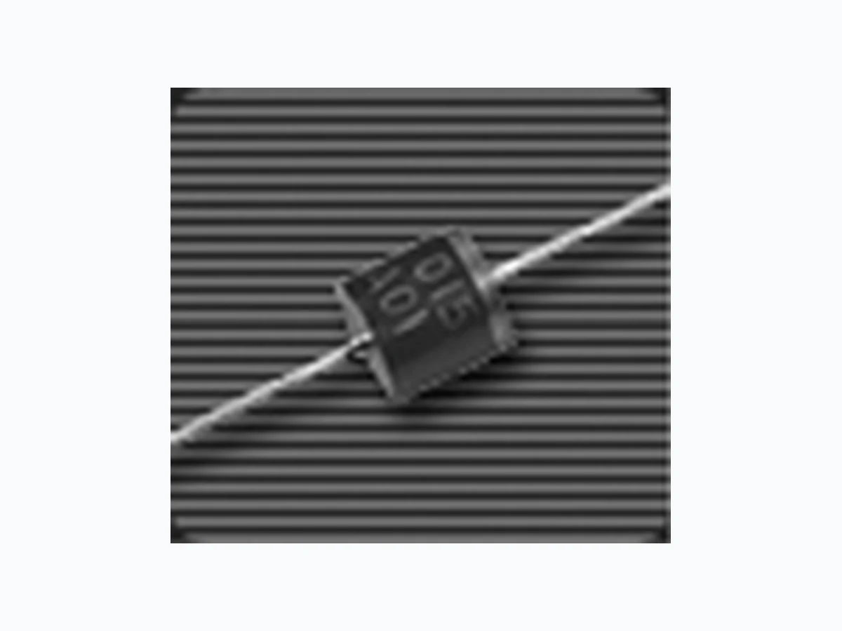
5KP5.0 GOOD-ARK
Document overview
- Manufacturer or author: Provided By digicamel.com
- PDF pages: 4
Technical content
scitsiretcarahClamrehTdnasgnitaRmumixaM Ratings at 25oC ambient temperature unless otherwise specified. Plastic package has Underwriters Laboratory Flammability Classification 94V-0 Glass passivated junction 5000W peak pulse power capability with a 10/1000ms waveform, repetition rate (duty cycle): 0.05% Excellent clamping capability Low incremental surge resistance Fast response time: theoretically (with no parisitic inductance) less than 1ps from 0 Volts to V (BR) for unidirectional and 5ns for bidirectional types. Devices with V (BR) > 10V ID are typically ID less than 1.0mA High temperature soldering guaranteed: 265oC/10 seconds, 0.375" (9.5mm) lead length, 5lbs. (2.3 kg) tension Case: Molded plastic body over glass passivated junction Terminals: Solder plated axial leads, solderable per MIL-STD-750, Method 2026 Polarity: The color band denotes the cathode, which is positive with respect to the anode under normal TVS operation Mounting Position: Any Weight: 0.07 ounce, 2.1 grams AC052PK5urht0.5PK5 srosserppuSegatloVtneisnarT V052ot0.5egatloVffo-dnatSW0005rewoPesluPkaeP retemaraPl obmySe ulaVt inU 0001/01ahtiwnoitapissidrewopeslupkaeP u mrofevaws )1( P MPP 0005muminiMW 0001/01ahtiwtnerruceslupkaeP u mrofevaws )1( I MPP elbaTtxeNeeSA noitapissidrewopetatsydaetS Tta L 57= o )mm5.9("573.0shtgneldael,C )2( P )VA(M 0.8W evaw-enisflahelgnissm3.8,tnerrucegrusdrawrofkaeP )3( I MSF 005s pmA A001taegatlovdrawrofsuoenatnatsnI )3( VF 5.3s tloV egnarerutarepmetegarotsdnanoitcnujgnitarepOT J T, GTS 571+ot55- oC Notes: 1. Non-repetitive current pulse, per Fig.3 and derated above T A=25oC per Fig. 2 3. Measured on 8.3ms single half sine-wave or equivalent square wave, duty cycle = 4 pulses per minute maximum. Devices for Bidirectional Applications characteristics apply in both directions.
(TA=25oC unless otherwise noted.) epyteciveD egatlovnwodkaerB V )RB( )stloV( )1( tseT tnerruc Ita T )Am( ffo-dnatS egatlov V MW )stloV( mumixaM esrever egakael Vta MW ID (u )A mumixaM eslupkaep tnerruc I MPP )2( )A( mumixaM gnipmalc egatlov Ita MPP VC )stloV( mumixaM erutarepmet tneiciffeoc Vfo )RB( /%( o )C.niM. xaM
(TA=25oC unless otherwise noted.) epyteciveD egatlovnwodkaerB V )RB( )stloV( )1( tseT tnerruc Ita T )Am( ffo-dnatS egatlov V MW )stloV( mumixaM esrever egakael Vta MW ID (u )A mumixaM eslupkaep tnerruc I MPP )2( )A( mumixaM gnipmalc egatlov Ita MPP VC )stloV( mumixaM erutarepmet tneiciffeoc Vfo )RB( /%( o )C.niM. xaM 001PK51 116 310 .50 010 .29 .729 710 11.0 A001PK51 113 210 .50 010 .29 .032 610 11.0 011PK52 219 410 .50 110 .25 .526 912 11.0 A011PK52 215 310 .50 110 .22 .827 712 11.0 A021PK53 317 410 .50 210 .24 .623 910 11.0 A031PK54 419 510 .50 310 .24 .429 020 11.0 A051PK57 615 810 .50 510 .20 .123 420 11.0 A061PK58 717 910 .50 610 .27 .919 520 11.0 A071PK59 819 020 .50 710 .25 .815 720 11.0 A081PK50 021 220 .50 810 .25 .712 920 11.0 A091PK51 123 320 .50 910 .25 .610 130 11.0 A052PK57 726 030 .50 520 .20 .215 240 11.0 Notes: 1. V(BR) measured after IT applied for 300us, IT=square wave pulse or equivalent 2. Surge current waveform per Fig. 3 and derate per Fig. 2 3. All terms and symbols are consistent with ANSI/IEEE CA62.35 4. For parts without A, the V BR is +10% The 5KP series of high power transient voltage suppressors were designed to be used on the output of switching power supplies. These devices may be used to replace crowbar circuits. Both the 5 and 10 percent voltage tolerances are referenced to the power supply output voltage level. They are able to withstand high levels of peak current while allowing a circuit breaker to trip or a fuse blow before shorting. This will enable the user to reset the breaker or replace the fuse and continue operation. For this type operation, it is recommended that a sufficient mounting surfa ce be used for dissipating the heat generated by the Transient Voltage Suppressor during the transient or over-voltage condition. Transient Voltage Suppressors are Silicon PN Junction devices designed for absorption of high voltage transients associated wit h power disturbances, switching and induced lighting effects. This series is available from 5.0 volts thru 110 volts. Application:
SEVRUCCITSIRETCARAHCDNASGNITAR (TA = 25oC unless otherwise noted)