
533_10 VISHAY
Document overview
- Manufacturer or author: Provided By www.digicamel.com(FREE DATASHEET DOWNLOAD SITE)
- PDF pages: 4
Technical content
Model 533, 534, 535 Vishay Spectrol Document Number: 57065 For technical questions, contact: sfer@vishay.com www.vishay.com Revision: 06-Apr-10 123 7/8" (22.2 mm) Multiturn Wirewound 533: 3 Turns/534: 10 Turns/535: 5 Turns Note
- The color of this product may eith er be black (US market) or blue (other regions)
FEATURES
- Bushing and servo mount designs available
- Special resistance tolerances to 1 %
- Rear shaft extensions and support bearing
- Metric shaft available
- Dual gang configuration and concentric shafts
- High torque, center tap, slipping clutch on request
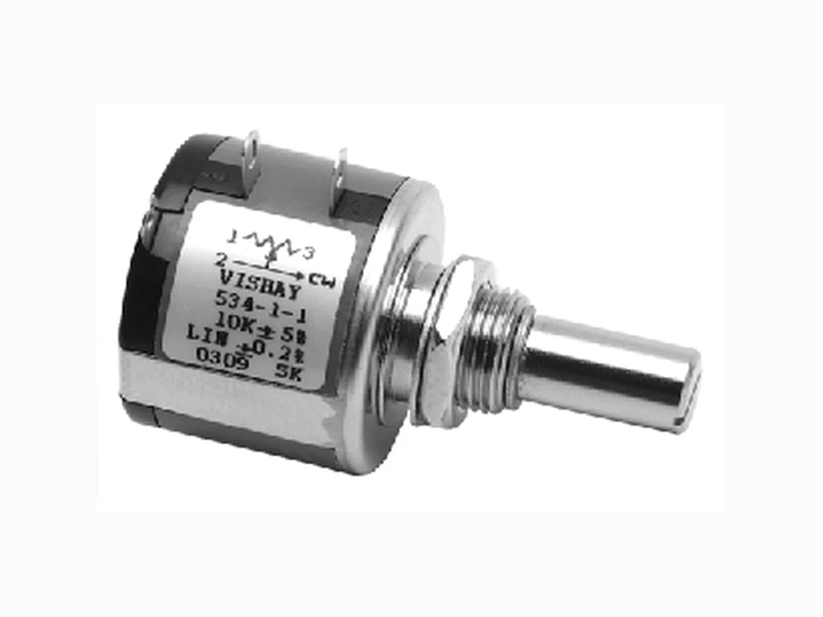
- Special markings and front shaft extensions RoHS COMPLIANT ELECTRICAL SPECIFICATIONS PARAMETER MODEL 533 MODEL 534 MODEL 535 Resistance Range - Standard Values 50 Ω to 20 kΩ 100 Ω to 100 kΩ 50 Ω to 50 kΩ Capability Range 5 Ω to 60 kΩ 10 Ω to 200 kΩ 5 Ω to 100 kΩ Standard Tolerance ± 5 % ± 5 % ± 5 % Linearity (Independent) ± 0.25 % ± 0.25 % ± 0.25 % Noise 100 Ω ENR 100 Ω ENR 100 Ω ENR Rotation (Electrical and Mechanical) 1080° + 10° - 0° 3600° + 10° - 0° 1800° + 10° - 0° Power Rating (at 70 °C) 1.0 W 2.0 W 1.5 W Insulation Resistance 1000 M Ω minimum 500 VDC Dielectric Strength 1000 V RMS minimum 60 Hz Absolute Minimum Resistance Not to exceed linearity x total resistance or 1 Ω, whichever is greater Temperature Coefficient 20 ppm/° C (standard values, wire only) End Voltage 0.25 % of total applied voltage, maximum Phasing CCW end points - section 2 phased to section 1 within ± 2° Taps Center tap only MARKING Unit Identification Manufacturer’s name and model number, resistance value and tolerance, linearity specification date code and terminal identification RESISTANCE VALUES Ohms 533: 50R, 100R, 200R, 500R, 1K, 2K, 5K, 10K, 20K 534: 100R, 200R, 500R, 1K, 2K, 5K, 10K, 20K, 50K, 100K 535: 50R, 100R, 200R, 500R, 1K, 2K, 5K, 10K, 20K, 50K ORDERING INFORMATION/DESCRIPTION The Models 533 (3 turns), 534 (10 turns) and 535 (5 turns) can be ordered by stating
534 B 2 10K 20K 5 % C BO10 e4
LINEARITY PACKAGING LEAD FINISH B: Bushing S: Servo ± 0.25 % (STD) Box of 10 pieces SAP PART NUMBERING GUIDELINES
534 B 2 103 203 J C B10
B: Bushing S: Servo 103 = 10K 203 = 20K J: ± 5 % F: ± 1 % C: ± 0.25 % CUSTOM: L: ± 0.20 % D: ± 0.1 % Box of 10 pieces
Model 533, 534, 535 Vishay Spectrol 7/8" (22.2 mm) Multiturn Wirewound 533: 3 Turns/534: 10 Turns/535: 5 Turns www.vishay.com For technical questions, contact: sfer@vishay.com Document Number: 57065 SINGLE SECTION DIMENSIONS in inches (millimeters) Mounting hardware, washer and panel nut, nickel plated POWER RATING CHART MECHANICAL SPECIFICATIONS PARAMETER Bearing Type Bushing: Sleeve bearing Servo: Ball bearing Torque (Maximums): Starting Section 1 Section 2 534 0.5 oz. - in (36 g - cm) 0.9 oz. - in (65 g - cm) 0.7 oz. - in (50 g - cm) 1.1 oz. - in (79 g - cm) Torque (Maximums): Running Section 1 Section 2 534 0.4 oz. - in (28.80 g - cm) 0.7 oz. - in (50.40 g - cm) 0.6 oz. - in (43.20 g - cm) 0.9 oz. - in (64.8 g - cm) Weight (Maximums) Section1 Section 2 0.75 oz. (21.26 g) 1.25 oz. (35.44 g) Stop Strength 75 oz. - in (static) (5.4 kg - cm) Ganging 2 sections maximum 1 3 CW SCHEMATIC 0.750 (19.05) ± 0.015 0.312 (7.92) ± 0.015 0.062 (1.57) 0.200 MIN. (5.08) Ø 0.875 (22.22) ± 0.015 0.030 MAX. (0.76) 0.812 (20.62) ± 0.031 Ø 0.2497 (6.34) + 0.0000 - 0.0003 0.032 x 0.032 (0.81) x (0.81) DP ± 0.010 3/8 - 32UNEF - 2A Ø 0.4062 (10.32) + 0.0000 - 0.0020 9 mm x 0.75 P Ø 6.00 mm 12 3 SCREWDRIVER SLOT + 0.000 - 0.0003 ± 0.031 0.062 (1.57) Ø 0.7500 (19.05) + 0.0000 - 0.0005 Ø 0.875 (22.22) Ø 0.1248 (3.17) + 0.0000 - 0.0003 0.057 (1.45) MIN. 0.300 (7.62) MIN. Ø 0.750 (19.05) MAX. Ø 0.875 (22.22) ± 0.015 2 1 0.062 (1.57) 30° TYP. R 0.625 MAX. (15.88) BUSHING MOUNT MODEL: 534B SERVO MOUNT MODEL: 534S METRIC SHAFT: 534B...8872 RATED POWER IN W 02 0 4 06 0 80 100 120 140 160 534 535 533 AMBIENT TEMPERATURE IN °C ENVIRONMENTAL SPECIFICATIONS Vibration 15 g thru 2000 Hz Shock 50 g Rotational Life (Shaft Revolution) 533 534 534 (Servo) 535 300 000 1 000 000 > 1 000 000 500 000 Load Life 900 h Temperature Range - 55 °C to + 125 °C
Model 533, 534, 535 7/8" (22.2 mm) Multiturn Wirewound 533: 3 Turns/534: 10 Turns/535: 5 Turns Vishay Spectrol Document Number: 57065 For technical questions, contact: sfer@vishay.com www.vishay.com Revision: 06-Apr-10 125 RESISTANCE ELEMENT DATA RESISTANCE VALUE (Ω) RESOLUTION % OHMS PER TURN MAXIMUM CURRENT AT 70 °C AMBIENT (mA) MAXIMUM VOLTAGE ACROSS COIL (V) 533 534 535 533 534 535 533 534 535 533 534 535 533 534 535
Document Number: 91000 www.vishay.com Revision: 11-Mar-11 1 Disclaimer Legal Disclaimer Notice Vishay ALL PRODUCT, PRODUCT SPECIFICATIONS AND DATA AR E SUBJECT TO CHANGE WITHOUT NOTICE TO IMPROVE RELIABILITY, FUNCTION OR DESIGN OR OTHERWISE. Vishay Intertechnology, Inc., its affiliates, agents, and employees, and all persons acting on its or their behalf (collectivel y, “Vishay”), disclaim any and all liability for any errors, inaccuracies or incompleteness contained in any datasheet or in any other disclosure relating to any product. Vishay makes no warranty, representation or guarantee regarding the suitability of the products for any particular purpose or the continuing production of any product. To the maximum extent permitted by applicable law, Vishay disclaims (i) any and all liability arising out of the application or use of any product, (ii) any and all liability, incl uding without limitation specia l, consequential or incidental dama ges, and (iii) any and all impl ied warranties, including warran ties of fitness for particular purpose, non-infringement and merchantability. Statements regarding the suitability of pro ducts for certain types of applications are based on Vishay’s knowledge of typical requirements that are often placed on Vishay products in gene ric applications. Such statements are not binding statements about the suitability of products for a partic ular application. It is the customer’s responsibility to validate that a particu lar product with the properties described in th e product specification is su itable for use in a particul ar application. Parameters provided in datasheets an d/or specifications may vary in different applications and perfo rmance may vary over time. All operating parameters, including typical pa rameters, must be validated for each customer application by the customer’s technical experts. Product specifications do not expand or otherwise modify Vishay’s term s and conditions of purchase, including but not limited to the warranty expressed therein. Except as expressly indicated in writing, Vishay products are not designed for use in medical, life-saving, or life-sustaining applications or for any other application in which the failure of the Vishay product co uld result in person al injury or death. Customers using or selling Vishay products not expressly indicated for use in such applications do so at their own risk and agree to fully indemnify and hold Vishay and it s distributors harmless from and against an y and all claims, liabilities, expenses and damages arising or resulting in connection with such use or sale, including attorneys fees, even if such claim alleges that Vishay or its distributor was negligent regarding the design or manufacture of the part. Please contact authorized Vishay personnel to obtain written terms and conditions regarding products designed for such applications. No license, express or implied, by estoppel or otherwise, to any intellectual property rights is granted by this document or by any conduct of Vishay. Product names and markings noted herein may be trademarks of their respective owners.