

 Download PDF
5150E OHMITE
Document overview
- PDF pages: 1
Technical content
Page 1
Rheostat and Tap Switch Hardware
Knobs, Dials, Mounting Fasteners
R h e o s t a t t a n d e m c o u p l i n g k i t s
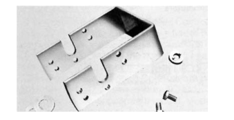
Ohmite coupling kits permit tandem mounting of two rheostat
units. A coupling fastens to the shaft of the back unit; projections
on the coupling engage the recesses in the driving hub of the
front unit.
Each kit consists of a steel “U” frame, a coupling with set
screw, mica washer, allen wrench and instructions.
Part No. Front mount models
Rear mount models
Max. panel thickness 5/32”
6532
H, J
H, J, G, K, L
1/8”
6533
G, K, L
H, J, G, K, L
1/16”
6591
E
E
R h e o s t a t r e p a i r k i t s
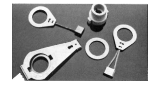
Electrical contact replacement kit. Kit
Part No. Rheostat model
includes contact/slip ring assemblies (for
7070
P
7071
N
round and ribbon wire rheostats), copper
7072
R
graphite washer, spring arm and hub.
7074
U
Instructions included.
E x t r a m o u n t i n g h a r d w a r e
Kit contains 25 each, nuts and lock washers for panel mounting
units.
Part No. For model 7090 E 7091 H, J, G, K, L, 111, 212, 711
= Standard values = Non-standard values subject to minimum handling charge per item
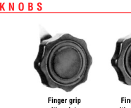
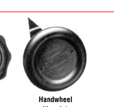
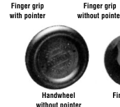
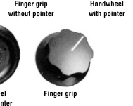
Any knob can be used with any rheostat and tap switch model
which has the corresponding shaft diameter. Knobs are fas-
tened to shafts with slotted set screws.
Slotted Hex socket
Knob Hole Fits
set screw set socket
Description
dia. dia. model
Bar knob, 21/4” long
1/4” H, J, G, K, L —
5102 — Bar knob, 11/4” long
1/4” H, J, G, K, L —
5103 5103A 5104 5104A Handwheel with pointer 31/4” 3/8” P, N, R, U
Handwheel without pointer 31/4” 3/8” P, N, R, U
5105 — 5106 5106A Handwheel with pointer 31/4” 1/4” H, J, G, K, L
Handwheel without pointer 31/4” 1/4” H, J, G, K, L
5107 — 5109 5109A Finger-grip with pointer 15/8” 1/4” H, J, G, K, L 5110 5110A Finger-grip without pointer 15/8” 1/4” H, J, G, K, L 5111 5111A Finger-grip with pointer 23/8” 1/4” H, J, G, K, L 5112 5112A Finger-grip without pointer 23/8” 1/4” H, J, G, K, L
11/2” 1/4” H, J, G, K, L
5150 5150A
Finger-grip
3/4” 1/8” C, E
5151 —
Finger-grip
5152A Like 5104 (shorter pointer) 31/4” 1/4” H, J, G, K, L —
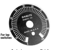
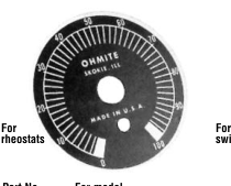
D i a l s
Handsomely finished, black-enameled, aluminum dials for
Ohmite rheostats and tap switches. Figures and lines are etched
on a black background for contrast and ease of readability. On
rheostat dials, divisions indicating approximate percentage of
rheostat resistance in circuit are marked from 0 to 100. On tap
switch dials, Number of dial positions are identical with number
of switch positions.
Part No. For model
For knob
Dial dia. 11/4”
5007 C, E
5151
23/16”
5000 H, J, G, K, L
5150, 5116, 5103
51/2”
5001 P, N, R, U
5104, 5106
23/4”
5002-\* 111, 212 (single), 312 (single)
5109, 5116, 5150
33/4”
5003-\* 212 (tandem), 312 (tandem), 412
5111, 5152A
51/2”
5004-\* \* Specify number of positions as suffix.
82 Ohmite Mfg. Co. 1-866-9-OHMITE • Int’l 1-847-258-0300 • Fax 1-847-574-7522 • www.ohmite.com • info@ohmite.com