

 Download PDF
5105625 PHOENIX
Document overview
- Manufacturer or author: Provided By www.digicamel.com(FREE DATASHEET DOWNLOAD SITE)
- PDF pages: 6
Technical content
- Electrical isolation without additional power supply
- Current signals 0(4)...20 mA
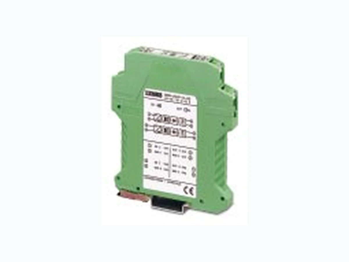
- 1-, 2- and 4-channel versions 1. Description MCR-1,2,4CLP-I/I-00 passive isolators are used for the electrical isolation and processing of analog 0(4)… 20 mA standard current signals. The blocks provide electrical isolation between the control electronics and process I/O. In addition, interference signals above 75 Hz are effectively suppressed. Input and output circuit do not require separate auxiliary power. The modules obtain this power from the input signal. The modules are snapped onto symmetrical DIN rails in accordance with EN 50 022. When using passive isolators, ensure that the current-driving voltage of the measuring transducer U B is sufficient for driving the maximum current of 20 mA over the passive isolator with the power loss of U V = 2.5 V and the load R B This means: U B U E = 2.5 V + 20 mA R B I I R BU E U B I MCR-1CLP I II UV = 2.5 V The graphic shows the input voltage of U E dependant on the load R B considering the power loss U V If you know your load, the lowest voltage, which the sensor should use to drive a maximum current of 20 mA via passive isolators and loads, can be read from the Y -axis. Input voltage depending on the load at I A = 20 mA 1000 800 600 400 200 U E BR / 0 U V = 2,5 V / V W Multi-Channel Passive Isolator MCR-...CLP-I/I-00 Headqua rters: © Phoenix Contact GmbH & Co. KG • Flachsmarktstraße 8 • 32825 Blomberg • Germa ny Phone +49 - 52 35 - 3 00 • Fax +49 - 52 35 - 34 12 00 • www.phoenixcontact.com
PHOENIX CONTACT page 2 of 6 Multi-Channel Passive Isolator – MCR-...CLP-I/I-00 2. Technical Data solid flexible [mm ] AWG Connection data 0.2-2.5 0.2-2.5 24-14
Description
for electrical isolation of current signals without power supply 1-channel 12.5 mm (0.492 in.) Technical Data Per Channel Input Input signal Power loss Maximum input current/overload Maximum input voltage/overload Voltage limitation with zener diode Output Output signal Maximum output signal Maximum load Ripple General Data Transmission error Additional error every 100 W load Temperature coefficient Cut-off frequency (3 dB) Response time (10-90%) Test voltage Ambient temperature range Housing material Input/output Channel/channel M 3 MCR-1CLP-I/I-00 1-channel Aa Type Order No. Pcs. Pkt. MCR-1CLP-I/I-00 28 14 01 6 0(4)…20 mA
2.5 V at I = 20 mA
30 V / 30 V
0(4)…20 mA < 50 mA 1375 W at I = 20 mA output signal < 5 mV rms 0.1% of the final value 0.02% of the measured value 0.002%/K of the measured value / 100 W load < 75 Hz at I = 20 mA and maximum load 5 ms at 500 W load
510 V, 50 Hz, 1 minute
– 10°C to +70°C (14˚F to 158˚F) Polyamide PA, unarmored 114.5 (4.508 in.) (3.898 in.) IN OUT (–) GND (+) 0-20mA1 6(–) GND (+) 0-20mA
PHOENIX CONTACT page 3 of 6 Multi-Channel Passive Isolator – MCR-...CLP-I/I-00 solid flexible [mm ] AWG Connection data 0.2-2.5 0.2-2.5 24-14 for electrical isolation of current signals without power supply 2-channel 12.5 mm (0.492 in.) Technical Data per Channel Input Input signal Power loss Maximum input current/overload Maximum input voltage/overload Voltage limitation with zener diode Output Output signal Maximum output signal Maximum load Ripple General Data Transmission error Additional error every 100 W load Temperature coefficient Cut-off frequency (3 dB) Response time (10-90%) Test voltage Ambient temperature range Housing material Input/output Channel/channel M 3 MCR-2CLP-I/I-00 2-channel Aa Type Order No. Pcs. Pkt. MCR-2CLP-I/I-00 28 14 02 9 0(4)…20 mA 0(4)…20 mA < 50 mA 1375 W at I = 20 mA output signal < 5 mV rms 0.1% of the final value 0.02% of the measured value 0.002%/K of the measured value / 100 W load < 75 Hz at I = 20 mA and maximum load 5 ms at 500 W load 2 kV, 50 Hz, 1 minute – 10°C to +70°C (14˚F to 158˚F) Polyamide PA, unarmored 114.5 (4.508 in.) (3.898 in.) IN OUT (–) GND (+) 0-20mA (–) GND (+) 0-20mA (–) GND (+) 0-20mA (–) GND (+) 0-20mA
PHOENIX CONTACT page 4 of 6 Multi-Channel Passive Isolator – MCR-...CLP-I/I-00 solid flexible [mm ] AWG Connection data 0.2-2.5 0.2-2.5 24-14 for electrical isolation of current signals without power supply 4-channel 22.5 mm (0.886 in.) Technical Data per Channel Input Input signal Power loss Maximum input current/overload Maximum input voltage/overload Voltage limitation with zener diode Output Output signal Maximum output signal Maximum load Ripple General Data Transmission error Additional error every 100 W load Temperature coefficient Cut-off frequency (3 dB) Response time (10-90%) Test voltage Ambient temperature range Housing material Input/output Channel/channel M 3 MCR-4CLP-I/I-00 4-channel Aa Type Order No. Pcs. Pkt. MCR-4CLP-I/I-00 28 14 04 5 0(4)…20 mA 0(4)…20 mA < 50 mA 1375 W at I = 20 mA output signal < 5 mV rms 0.1% of the final value 0.02% of the measured value 0.002%/K of the measured value / 100 W load < 75 Hz at I = 20 mA and maximum load 5 ms at 500 W load 2 kV, 50 Hz, 1 minute – 10°C to +70°C (14˚F to 158˚F) Polyamide PA, unarmored 114.5 (4.508 in.) (3.898 in.) IN OUT (–) GND (+) 0-20mA (–) GND (+) 0-20mA (–) GND (+) 0-20mA (–) GND (+) 0-20mA (–) GND (+) 0-20mA (–) GND (+) 0-20mA (–) GND (+) 0-20mA (–) GND (+) 0-20mA
PHOENIX CONTACT page 5 of 6 Multi-Channel Passive Isolator – MCR-...CLP-I/I-00 3. Connection Notes To ensure problem-free operation, the signal source for the passive isolator must supply a sufficiently high voltage: U S U RL + U E = U RL1 + U RL2 + U T + U B The maximum load to be driven depends on the input voltage UE of the passive isolator. Calculation: URL = U RL1 + U RL2 = 20 mA * R L U E T + U B = 2.5 V + 20 mA * R B U E = Input voltage at passive isolator U T = Voltage drop at passive isolator U B = Voltage drop at output load U RL = Voltage drop via both incoming cables A = Conductor cross-section in mm l = Line length between signal source and passive isolator g = Electr. conductivity [Cu = 56 m/ W * mm R B = Load impedance cccc Conforms to the EMC Directive 89/336/EEC and the Low Voltage Directive 73/23/EEC EMC (Electromagnetic Compatibility) Noise immunity in accordance with EN 50082-2
- Electrostatic discharge (ESD)
- Electromagnetic HF field Amplitude modulation Pulsed modulation
- Fast transients (burst)
- Surge current load (surge)
- Conducted interference Noise emission in accordance with EN 50081-2 EN 61000 corresponds to IEC 1000/ EN 55022 corresponds to CISPR22 Criterion A: Normal operating characteristics within the specified limits. Criterion B: Temporary adverse effects on the operating characteristics that the device corrects independently. Class B: Industrial and domestic applications 2 • I g • AR L = Input voltage depending on the load at I A = 20 mA EN 61000-4-2 EN 61000-4-3 EN 61000-4-4 EN 61000-4-5 EN 61000-4-6 EN 55022 8 kV air discharge
10 V/m
Input/output: 2 kV/42 W Input/output 10 V Class B U E I I 0…20mA MCR-1CLP U S U TU RL1 U RL2 RL1 RL2 RB U B IB (0…20mA) IN OUTSignal source 1000800600400200 U E BR / 0 U V = 2,5 V / V W
PHOENIX CONTACT page 6 of 6 Multi-Channel Passive Isolator – MCR-...CLP-I/I-00 4. Application Example: Flow Rate Measurement MCR-1CLP-I/I-00 2GND 1 I GND 2 IN OUT 0...20mA 0...20mA24V Magnetic inductive flow meter Control system Ó PHOENIX CONTACT 15.06.00 TNR: 5105625-00 http://www.phoenixcontact.com