
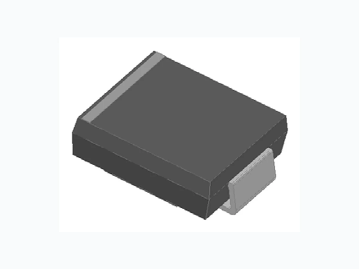
5.0SMDJ RFE
Document overview
- Manufacturer or author: Provided By digicamel.com
- PDF pages: 5
Technical content
Peak power dissipation, with a 10/1000 s waveform 1 2 PPPM W 5000 Peak pulse current, with a 10/1000 s waveform IPPM A See Next Table Power dissipation, on infinite heat sink at TL=75 PD W 6.5 Peak forward surge current, 8.3 ms single half sine-wave unidirectional only IFSM A 300 Operating junction and storage temperature range TJ,TSTG -55 to +150 Surface Mount Transient Voltage Suppressor Diodes
5.0 SMDJ Series DO-214AB (SMC)
RFE International • Tel (949) 833-1988 • Fax (949) 833-1788 • E-mail sales@rfeinc.com MAXIMUM RATINGS (Ta=25 Unless otherwise specified PARAMETER SYMBOL UNIT Conditions VALUE Thermal Resistance(Typical) R J-A (5) /W 57 tneibma ot noitcnuj R J-L (5) /W 51 dael ot noitcnuj R J-C (5) /W 31 esac ot noitcnuj Notes: (1) Non-repetitive current pulse, per Fig. 3 and derated above TA= 25 per Fig.2. (2) Mounted on 0.31 x 0.31" (8.0 x 8.0 mm) copper pads to each terminal (3) Measured on 8.3ms single half sine-wave or equivalent square wave,duty cycle=4 pulses per minute maximum. (4) VF=3.5V Max for devices of VBR 85V and VF=5.0V Max for devices of VBR 85V. (5) Mounted on minimum recommended pad layout.
FEATURES
UL recognition, file # E517074
5000 W peak pulse power capability with a
Uni and Bidirectional unit Excellent clamping capability Very fast response time Meets MSL level 1 Use in sensitive electronics protection against voltage transients induced by inductive load switching and lighting on ICs, MOSFET, signal lines of sensor units for consumer, computer, industrial, telecommunication. Package: DO-214AB (SMC) Molding compound meets UL 94 V-0 flammability rating, RoHS-compliant Terminals: Tin plated leads, solderable per J-STD- 002 and JESD22-B102 Polarity: For uni-directional types the band denotes cathode end, no marking on bi-directional types THERMAL CHARACTERISTICS (Ta=25 Unless otherwise specified
(Uni) Part Number (Bi) Breakdown Voltage VBR@IT Maximum Reverse Leakage IR @ VRWM ( A) Working Peak Reverse Voltage VRWM (V) Maximum Reverse Surge Current IPP (2) (A) Maximum Clamping Voltage Vc @ IPP (V) Min(V) Max (V) IT (1) (mA) Surface Mount Transient Voltage Suppressor Diodes ELECTRICAL CHARACTERISTICS (Ta=25 Unless otherwise specified PARAMETER SYMBOL UNIT VALUE Maximum instantaneous forward voltage at 100A for unidirectional only (4) VFM V 3.5/5.0 S-S003 16-02-2022 Page 2 of 5 RFE International • Tel (949) 833-1988 • Fax (949) 833-1788 • E-mail sales@rfeinc.com
(Uni) Part Number (Bi) Breakdown Voltage VBR@IT Maximum Reverse Leakage IR @ VRWM ( A) Working Peak Reverse Voltage VRWM (V) Maximum Reverse Surge Current IPP (2) (A) Maximum Clamping Voltage Vc @ IPP (V) Min(V) Max (V) IT (1) (mA) Notes: (1) Pulse Test tp 50ms Pulse test: tp 50ms. (2) Surge current waveform per Fig. 3 and derated per Fig.2. PREFERED P/N PACKAGE CODE UNIT WEIGHT(g) MINIMUM PACKAGE(pcs) INNER BOX QUANTITY(pcs) OUTER CARTON QUANTITY(pcs) DELIVERY MODE 5.0SMDJ SERIES F1 Approximate 0.270 3000 6000 42000 13” reel 0020 TJ PPP or IPP(%) FIG2: Pulse Power or Current vs. Initial Junction Temperature 100 175150125100755025 0.1 s 1 s 10 s 100 s 1.0ms 10ms 0.1 td( s) PPPM(KW) FIG1:Peak Pulse Power Rating Curve 1.0 100 Non-Repetitive Pulse Waveform shown in Fige.3 TA=25 Copper Pad Areas Surface Mount Transient Voltage Suppressor Diodes RFE International • Tel (949) 833-1988 • Fax (949) 833-1788 • E-mail sales@rfeinc.com ELECTRICAL CHARACTERISTICS (Ta=25 Unless otherwise specified PACKAGING INFORMATION CHARACTERISTICS (TYPICAL)
DO-214AB (SMC) Dim Min Max A 6.60 7.11 B 2.85 3.27 C 5.59 6.22 D 7.75 8.13 E 1.99 2.61 F 0.15 0.31 G 0.76 1.52 H 0.05 0.20 0.40 t ms IPPM(%) FIG3: Pulse Waveform 150 100 3.02.01.0 TJ=25 Pulse Width(td) is defined as the Point where the Peak Current Decays to 50% of IPPM 10/1000 s Waveform as Defined by R.E.A. tr=10 s Peak Value IPPM Half Value - IPP IPPM td 0.001 0.01 0.1 1 10 1000 0.1 tp(s) Rth( /W) FIG4:Typical Transient Thermal Impedance 100 100 Number of Cycles IFSM(A) FIG5: Maximum Non-Repetitive Surge Current 001010 250 200 300 100 150 TJ=TJMax. 8.3ms Single Half Sine-Wave PD(W) TL( ) FIG6:Steady State Power Dissipation 20025 50 75 100 125 150 175 Dimensions in millimeters DO-214AB(SMC) Surface Mount Transient Voltage Suppressor Diodes RFE International • Tel (949) 833-1988 • Fax (949) 833-1788 • E-mail sales@rfeinc.com CHARACTERISTICS (TYPICAL) OUTLINE DIMENSIONS
P1 9.9 P2 3.84 Q1 3.03 Q2 3.82 Dimensions in millimeters Surface Mount Transient Voltage Suppressor Diodes RFE International • Tel (949) 833-1988 • Fax (949) 833-1788 • E-mail sales@rfeinc.com SUGGESTED PAD LAYOUT