

 Download PDF
5.0SMDJ-AT UNSEMI
Document overview
- Manufacturer or author: Provided By digicamel.com
- PDF pages: 5
Technical content
Features
Description
Applications
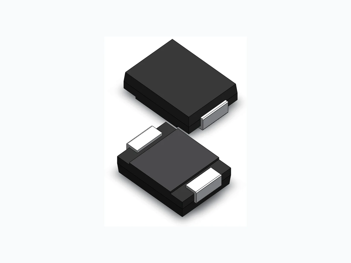
Revision March 1,2022 Surface Mount Transient Voltage Suppressors www.unsemi.com.tw 5000W www.unsemi.com.tw 5000 6.5 - 55 to +150 - 55 to +150 PPPM PM(AV) TJ , TSTG TOP Peak power dissipation with a 10/1000us waveform Steady state power dissipation at TL=75℃ Junction and Storage temperature range Operating temperature range W W Parameter Symbol Value Unit Maximum Ratings and Thermal Characteristics(TA=25℃ unless otherwise noted) For technical questions, contact: tech@unsemi.com.tw Specifications are subject to change without notice. Please refer to www.unsemi.com.tw for current information.1/4 Mechanical Data Package: SMC/DO-214AB Case Material: “Green” Molding Compound. UL Flammability Classification Rating 94V-0 Polarity:Color band denotes cathode except bi-directional models Weight: 0.3g Terminal Connections: See Diagram Below Marking Information: See Below Glass passivated junction Excellent clamping capability Repetition rate (duty cycle): 0.01% Low profile package and low inductance 5000W Peak Pulse power capability at 10×1000μs waveform. Fast response time: typically less than 1.0ps from 0V to VBR min. High temperature soldering: 260℃/10s at terminals. Plastic package has Underwriters Laboratory Flammability 94V-0 Matte tin lead–free Plated Halogen free and RoHS compliant For surface mounted applications in order to optimize board space High reliability application and automotive grade AECQ101qualified . I/O Interface. AC/DC Power supply Low frequency signal transmission line (RS232, RS485, etc.) Cathode Bi-directional Anode Uni-direction Functional Diagram Uni-directional Bi-directional
VRWM (V) Breakdown Voltage VBR (V) @IT Maximum Clamping Voltage VC @IPP (V) Maximum Peak Pulse Current IPP (A) Maximum Reverse Leakage IR @VRWM (μA) Test Current IT (mA) MIN MAX Marking Uni Bi 100 110 120 130 150 160 170 180 190 800 200 100 19.9 23.2 24.4 26.0 27.6 29.2 32.4 35.5 38.9 42.1 45.4 48.4 53.3 58.1 64.5 69.4 72.7 77.4 82.4 87.1 93.6 96.8 103.0 113.0 121.0 126.0 137.0 146.0 162.0 177.0 193.0 209.0 243.0 259.0 275.0 292.0 308.0 5.0SMDJ12A-AT 5.0SMDJ14A-AT 5.0SMDJ15A-AT 5.0SMDJ16A-AT 5.0SMDJ17A-AT 5.0SMDJ18A-AT 5.0SMDJ20A-AT 5.0SMDJ22A-AT 5.0SMDJ24A-AT 5.0SMDJ26A-AT 5.0SMDJ28A-AT 5.0SMDJ30A-AT 5.0SMDJ33A-AT 5.0SMDJ36A-AT 5.0SMDJ40A-AT 5.0SMDJ43A-AT 5.0SMDJ45A-AT 5.0SMDJ48A-AT 5.0SMDJ51A-AT 5.0SMDJ54A-AT 5.0SMDJ58A-AT 5.0SMDJ60A-AT 5.0SMDJ64A-AT 5.0SMDJ70A-AT 5.0SMDJ75A-AT 5.0SMDJ78A-AT 5.0SMDJ85A-AT 5.0SMDJ90A-AT 5.0SMDJ100A-AT 5.0SMDJ110A-AT 5.0SMDJ120A-AT 5.0SMDJ130A-AT 5.0SMDJ150A-AT 5.0SMDJ160A-AT 5.0SMDJ170A-AT 5.0SMDJ180A-AT 5.0SMDJ190A-AT 5.0SMDJ12CA-AT 5.0SMDJ14CA-AT 5.0SMDJ15CA-AT 5.0SMDJ16CA-AT 5.0SMDJ17CA-AT 5.0SMDJ18CA-AT 5.0SMDJ20CA-AT 5.0SMDJ22CA-AT 5.0SMDJ24CA-AT 5.0SMDJ26CA-AT 5.0SMDJ28CA-AT 5.0SMDJ30CA-AT 5.0SMDJ33CA-AT 5.0SMDJ36CA-AT 5.0SMDJ40CA-AT 5.0SMDJ43CA-AT 5.0SMDJ45CA-AT 5.0SMDJ48CA-AT 5.0SMDJ51CA-AT 5.0SMDJ54CA-AT 5.0SMDJ58CA-AT 5.0SMDJ60CA-AT 5.0SMDJ64CA-AT 5.0SMDJ70CA-AT 5.0SMDJ75CA-AT 5.0SMDJ78CA-AT 5.0SMDJ85CA-AT 5.0SMDJ90CA-AT 5.0SMDJ100CA-AT 5.0SMDJ110CA-AT 5.0SMDJ120CA-AT 5.0SMDJ130CA-AT 5.0SMDJ150CA-AT 5.0SMDJ160CA-AT 5.0SMDJ170CA-AT 5.0SMDJ180CA-AT 5.0SMDJ190CA-AT 5PDZT 5PEGT 5PEKT 5PEMT 5PEPT 5PERT 5PEVT 5PEXT 5PEZT 5PFET 5PFGT 5PFKT 5PFMT 5PFPT 5PFRT 5PFTT 5PFVT 5PFXT 5PFZT 5PGET 5PGGT 5PGKT 5PGMT 5PGPT 5PGRT 5PGTT 5PGVT 5PGXT 5PGZT 5PHET 5PHGT 5PHKT 5PHMT 5PHPT 5PHRT 5PHTT 5PHVT 5BDZT 5BEGT 5BEKT 5BEMT 5BEPT 5BERT 5BEVT 5BEXT 5BEZT 5BEET 5BFGT 5BFKT 5BFMT 5BFPT 5BFRT 5BFTT 5BFVT 5BFXT 5BFZT 5BGET 5BGGT 5BGKT 5BGMT 5BGPT 5BGRT 5BGTT 5BGVT 5BGXT 5BGZT 5BHET 5BHGT 5BHKT 5BHMT 5BHPT 5BHRT 5BHTT 5BHVT 13.3 15.6 16.7 17.8 18.9 20.0 22.2 24.4 26.7 28.9 31.1 33.3 36.7 40.0 44.4 47.8 50.0 53.3 56.7 60.0 64.4 66.7 71.1 77.8 83.3 86.7 94.4 100.0 111.0 122.0 133.0 144.0 167.0 178.0 189.0 201.0 211.0 14.7 17.2 18.5 19.7 20.9 22.1 24.5 26.9 29.5 31.9 34.4 36.8 40.6 44.2 49.1 52.8 55.3 58.9 62.7 66.3 71.2 73.7 78.6 86.0 92.1 95.8 104.0 111.0 123.0 135.0 147.0 159.0 185.0 197.0 209.0 222.0 233.0 252.0 216.0 205.0 193.0 181.0 172.0 155.0 141.0 129.0 119.0 110.0 103.0 93.9 86.1 77.6 72.1 68.8 64.7 60.7 57.5 53.5 51.7 48.6 44.3 41.4 39.7 36.5 34.3 30.9 28.3 26.0 24.0 20.6 19.3 18.2 17.5 16.5 5.0SMDJ-AT Series 5000W Surface Mount Transient Voltage Suppressors Revision March 1,2022 www.unsemi.com.tw For technical questions, contact: tech@unsemi.com.tw ROHS Electrical Characteristics (@=25℃ Unless Otherwise Specified ) Specifications are subject to change without notice. Please refer to www.unsemi.com.tw for current information.2/4 Note: (1) Add suffix ' CA ' after part number to specify Bi-directional devices (2) Suffix 'A ' denotes 5% tolerance device.
Revision March 1,2022 www.unsemi.com.tw Surface Mount Transient Voltage Suppressors ROHS Ratings and Characteristic Curves (TA=25°C unless otherwise noted) For technical questions, contact: tech@unsemi.com.tw Specifications are subject to change without notice. Please refer to www.unsemi.com.tw for current information.3/4 Part Numbering 5.0SMDJ-AT Series 5000W 5 . 0 S M D J X X C A - A T Vehicle 5% VBR Voltage Tolerance Bi-Directional VR Voltage Series Figure 2 - Pulse Derating CurveFigure 1 - Pulse Waveform T - Time (ms) Half Value IPPM (IPPM/2) 10/1000µsec. Waveform as defined by R.E.A Peak Value IPPM TR=10µsec TJ=25°C Pulse Width(td) is defined as the point where the peak current decays to 50% of IPPM 0 1.0 2.0 3.0 4.0 100 150IPPM - Peak Pulse Current, % IR SM I-V Curve Characteristics V VC VBR VR IR VFIT IPP Uni-directional VVC VBR VR VCVBRVR IR IR IT IT IPP IPP Bi-directional TA-Ambient temperature(°C) 0 25 50 75 100 125 150 175 100 Peak Pulse Power (PPP) or Current (IPP) Derating in Percentage %
Revision March 1,2022 www.unsemi.com.tw Surface Mount Transient Voltage Suppressors ROHS For technical questions, contact: tech@unsemi.com.tw Specifications are subject to change without notice. Please refer to www.unsemi.com.tw for current information.4/4 5.0SMDJ-AT Series 5000W Dimensions Dimensions Min Max MaxMin Inches Millimeters DO-214AB (SMC) Cathode Band A B C D E F G H I J K L 0.114 0.260 0.220 0.079 0.030 0.305 0.006 0.129 0.094 0.094 0.126 0.280 0.245 0.103 0.060 0.008 0.320 0.012 0.165 2.860 6.520 5.520 1.980 0.750 7.640 0.152 3.300 2.400 2.400 3.160 7.020 6.150 2590 1.510 0.203 8.020 0.305 4.200 Soldering Parameters Lead–free assembly 150°C 200°C 60 -180 Seconds 3°C/second max 5°C/second max 217°C 60 -150 Seconds 260 +0/-5°C 20 - 40 Seconds 6°C/second max 8 minutes Max 260°C Reflow Condition Pre Heat -Temperature Min (Ts(min)) -Temperature Max (Ts(max)) - Time (min to max) (Ts) Average ramp up rate ( Liquidus Temp TL) to peak TS(max) to TL - Ramp-up Rate Reflow - Temperature (TL) (Liquidus) - Time (min to max) (TS) Peak Temperature (TP) Do not exceed Time 25°C to peak Temperature (TP) Time within 5°C of actual peak Temperature (TP) Ramp-down Rate
Ordering Information
5.0SMDJ-AT Series Part Number Component Package Quantity Packaging Option Packaging Specification DO-214AB (SMC) 3,000 Tape & Reel -16mm/13″tape EIA STD RS-481 Ramp up TS(MAX) TS(MIN) Ramp down Time Temperature TP TL Critical Zone TL to TP TL Time 25℃ to peak Ts Preheat Tp
Revision March 1,2022 www.unsemi.com.tw For technical questions, contact: tech@unsemi.com.tw ROHS Specifications are subject to change without notice. Please refer to www.unsemi.com.tw for current information. Disclaimer ROHS UNSEMI RESERVES THE RIGHT TO MAKE CHANGE ON OUR PRODUTS , PRODUCTS SPECIFICATION AND DATA WITHOUT NOTICE TO IMPROVE RELIABILITY, FUNCTION OR DESIGN OR OTHERWISE. UN SEMICONDUCTOR LIMITED its affiliates, agents, and employees, and all persons acting on its or their behalf (collectively, “UNSEMI”)does not give any representations or warranties for any errors, inaccuracies or incompleteness contained in any datasheet or in any other disclosure relating to any product. In no event shall UNSEMI be liable for any indirect, incidental, punitive, special or consequential damages (including any and all implied warranties, warranties of fitness for particular purpose, non-infringement and merchantability.) whether or not such damages are based on tort (including negligence), warranty, breach of contract or any other legal theory. Statements regarding the suitability of products for certain types of applications are based on UNSEMI knowledge of typical requirements that are often placed on UNSEMI products in generic applications. Such statements are not binding, statements about the suitability of products for a particular application. It is the customer's responsibility to validate that a particular product with the properties described in the product specification is suitable for use in a particular application. Parameters provided in datasheets or specifications may vary in different applications and performance may vary over time. All operating parameters, including typical parameters, must be validated for each customer application by the customer's technical experts. Product specifications do not expand or otherwise modify UNSEMI's terms and conditions of purchase, including but not limited to the warranty expressed therein. Unless otherwise agreed in writing, UNSEMI product is not designed, authorized or warranted to be suitable for use in medical life-saving, or life-sustaining application , nor in applications where failure or malfunction of a UNSEMI product can reasonably be expected to result in personal injury, death or severe property or environmental damage. UNSEMI and its suppliers accept no liability for inclusion or use of UNSEMI products in such equipment or applications and therefore such inclusion and/or use is at the customer's own risk. All referenced brands, product names, service names and trademarks are the property of their respective owners.