
4DFA TOKO
Document overview
- Manufacturer or author: Provided By digicamel.com
- PDF pages: 3
Technical content
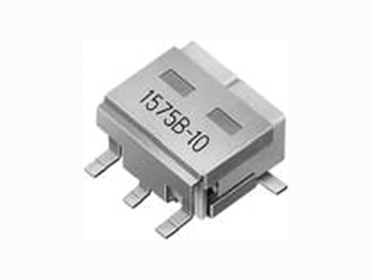
Dielectric Filters for Surface Mounting ༠ిମϑΟϧλ TYPE #4DFA #4DFB 17.5 14.5 11.5 1.5 *12.5 Max. GND GNDOUT IN *: Depends on Center Frequency. #4DFB-915E-10 Center Frequency: 915MHz ɹɹ Span: 200MHz Attenuation (dB) Return Loss (dB) Attenuation Return loss (Unit: mm) 12.5 5 9.6 GND GND GND OUT IN 1.5 *12.5 Max. TYPE #4DFA (2 Pole SMD Type) / #4DFB (3 Pole Type) Frequency Range: 700~2500MHz Temperature Range: − 40°C~+ 85°C Typical Characteristics දಛੑྫ SELECTION GUIDE FOR STANDARD DEVICES
- The Part Number shown in the table below are standard devices, which are readily available. TOKO will design and manufacture modified and custom devices with specific characteristics to meet your requiements. If you do not find the devices for your application in this catalog, please contact our sales or representative office.
- RoHS compliant ॴ·ͨ
- ྩରԠ *: Depends on Center Frequency. #4DFA-1575B-10 Center Frequency: 1,575.4MHz ɹɹ Span: 300MHz Attenuation (dB) Return Loss (dB) Attenuation Return loss (Unit: mm) #4DFA #4DFB TYPE #4DFA: SMD 2 Pole Designs TOKO Part Number Center Frequency (MHz) Insertion Loss (dB) Max. Ripple in BW (dB) Max. V.S.W.R. in BW Max. ApplicationBandwidth (fo ± MHz) Selectivity (dB) Min. (MHz) ೖग़ྗΠϯϐʔμϯεʗ*OQVU0VUQVUJNQFEBODFЊ
Dielectric Filters for Surface Mounting ༠ిମϑΟϧλ TYPE #4DFA #4DFB TYPE #4DFB: SMD 3 Pole Designs TOKO Part Number Center Frequency (MHz) Insertion Loss (dB) Max. Ripple in BW (dB) Max. V.S.W.R. in BW Max. ApplicationBandwidth (fo ± MHz) Selectivity (dB) Min. (MHz) ೖग़ྗΠϯϐʔμϯεʗ*OQVU0VUQVUJNQFEBODFЊ
- Reflow solder conditions
- Solderability When flux-mounted terminals are immersed in solder at following conditions, at least 95% of the surface should be covered by solder. Conditins leaded process : 230±5°C for 3±0.5 seconds lead free process : 260±5°C for 3±0.5 seconds
- Solder heat resistance No abnomalities under solder conditions of leaded process : 230±5°C for 5 seconds lead free process : 260±5°C for 5 seconds 2. Rinsing After Soldering, you should rinsing away the excess flux. Any commercially available rinsing agent may be used. 3. Other Precautions Perform soldering at as low a temperature as possible and for as short a time as possible. Make sure that the silver electrode of resonators is not covered by solder. Avoid applying external forces to terminals such as by bending or cutting them. 4. Iron Soldering Perform iron soldering with iron at following conditions. Conditins leaded process : 350±5°C for 5s. Max. lead free process : 390±5°C for 5s. Max. ͰΜͩதʹ ԖϑϦʔɹɿɹʶˆͷΜͩதʹʶඵਁ௮ Ͱҟৗͷͳ͍͜ͱɻ ચড় ͷϑϥοΫεͷચড়Λͯ͠Լ͍͞ɻ ༻Ͱ͖·͢ɻ ͬͯԼ͍͞ɻ ෦ʹ֎ྗΛՃ ͯ͜Μͩ ඵ Ҏɺճ ඵ Ҏɺճ Temperature profile (land seface temperature) ԹϓϩϑΝΠϧ (ϥϯυ෦ද໘Թ) *1 *2 ˆ 230 150 180 190 210 ˆ 260 150 180 220 240 *1 *2 for lead free processfor leaded process Pre-heat conditions ༧෦ *1ɿ150ʙ160ˆɹ60s. Max. *1ɿ150ʙ160ˆɹ 60ඵҎ Reflow conditions Ϧϑϩ෦ *2ɿ160ˆ Min.ɹ45s. Max. *2ɿ160ˆҎ্ɹ45ඵҎ *3ɿ200ˆ Min.ɹ30s. Max. *3ɿ200ˆҎ্ɹ30ඵҎ *4ɿ230±5ˆɹ5s. Max. *4ɿ230±5ˆɹ5ඵҎ Pre-heat conditions ༧෦ *1ɿ150ʙ180ˆɹ120s. Max. *1ɿ150ʙ180ˆɹ 120ඵҎ Reflow conditions Ϧϑϩ෦ *2ɿ180ˆ Min.ɹ150s. Max. *2ɿ180ˆҎ্ɹ150ඵҎ *3ɿ230ˆ Min.ɹ40s. Max. *3ɿ230ˆҎ্ɹ40ඵҎ *4ɿ255±5ˆɹ5s. Max. *4ɿ255±5ˆɹ5ඵҎ