


 Download PDF
48V MSYSTEM
Document overview
- PDF pages: 5
Technical content
Page 1
Bargraph Indicators 48 Series
BARGRAPH INDICATOR
[3] MOUNTING DIRECTION
V: Vertical H: Horizontal
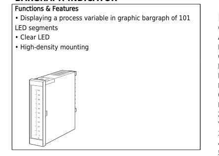
MODEL: 48V–[1][2][3][4]-[5]
ORDERING INFORMATION
- Code number: 48V-[1][2][3][4]-[5] Specify a code from below for each [1] through [5]. (e.g. 48V-2RRVA-R)
- Special input range (For codes Z & 0)
- Scale (e.g. 0 – 100 %)
[1]BARGRAPHS
1: Single 2: Dual
[2] LED COLOR
R: Red Y: Amber G: Green Dual (left/right) RR: Red / Red YY: Amber / Amber GG: Green / Green RY: Red / Amber RG: Red / Green YR: Amber / Red YG: Amber / Green GR: Green / Red GY: Green / Amber
[4] INPUT
Current A: 4 – 20 mA DC (Input resistance 10 Ω) B: 2 – 10 mA DC (Input resistance 20 Ω) C: 1 – 5 mA DC (Input resistance 39 Ω) D: 0 – 20 mA DC (Input resistance 10 Ω) E: 0 – 16 mA DC (Input resistance 12 Ω) F: 0 – 10 mA DC (Input resistance 20 Ω) G: 0 – 1 mA DC (Input resistance 200 Ω) H: 10 – 50 mA DC (Input resistance 3.9 Ω) Z: Specify current (See INPUT SPECIFICATIONS) Voltage 3: 0 – 1 V DC (Input resistance 100 kΩ) 4: 0 – 10 V DC (Input resistance 330 kΩ) 5: 0 – 5 V DC (Input resistance 250 kΩ) 6: 1 – 5 V DC (Input resistance 250 kΩ) 0: Specify voltage (See INPUT SPECIFICATIONS)
[5] POWER INPUT
AC Power K: 85 – 132 V AC (Operational voltage range 85 – 132 V, 47 – 63 Hz) L: 170 – 264 V AC (Operational voltage range 170 – 264 V, 47 – 63 Hz) DC Power R: 24 V DC (Operational voltage range 24 V ±15 %, ripple 10 %p-p max.)
GENERAL SPECIFICATIONS
Construction: Panel flush mounting Connection: M3 screw terminals (torque 0.6 N·m) Screw terminal: Chromated brass Housing material: ABS resin Isolation: Input 1 to input 2 to power Scale plate: Aluminium (white scale & characters on black base) Scale
- Characters including decimal points: Max. 6 charac. (48V-1, vertical mount.) Max. 4 charac. (48V-2, vertical mount.) Max. 4 charac. (48V-1, horizontal mount.) Max. 4 charac. (48V-2, horizontal mount.)
- Divisions: 22 – 54.9
- Engineering unit: Max. 8 charac. (48V-1, vertical mount.) Max. 5 charac. (48V-2, vertical mount.) Max. 8 charac. (48V-1, horizontal mount.)
ES-9311 Rev.13 Page 1/5
Page 2
Max. 3 charac. (48V-2, horizontal mount.) If there is only one engineering unit with dual bargraph type, the position and maximum number of characters for single type are applied. Bargraph: 101-segment LED, 100 mm (3.96”) long, 1.5 mm (.06”) wide
INPUT SPECIFICATIONS
■ DC Current: 0 – 50 mA DC; input resistor incorporated Minimum span: 1 mA 0 % input: 0 mA DC ■ DC Voltage: 0 – 10 V DC Minimum span: 1 V 0 % input: 0 V DC
INSTALLATION
Power consumption
- AC: Approx. 3.5 VA (single) or 5.5 VA (dual)
- DC: Approx. 2 W (single) or 4 W (dual) Operating temperature: 0 to 50°C (32 to 122°F) Operating humidity: 40 to 80 % RH (non-condensing) Mounting: Panel flush mounting Weight: 290 g (0.64 lbs) for 48V-1, DC powered 320 g (0.71 lbs) for 48V-1, AC powered 340 g (0.75 lbs) for 48V-2, DC powered 370 g (0.82 lbs) for 48V-2, AC powered
PERFORMANCE in percentage of span
Accuracy: ±1 % ±1 digit Response time: 0.5 sec. Insulation resistance: ≥ 50 MΩ with 500 V DC (input or power to ground) Dielectric strength: 2000 V AC @1 minute (input or power to ground) 1500 V AC @ 1 minute (input to AC power) 500 V AC @ 1 minute (input to DC power) 500 V AC @ 1 minute (input 1 to input 2)
ES-9311 Rev.13 Page 2/5
Page 3
STANDARD SCALE & UNIT EXAMPLES
■ DIVISIONS Number of divisions depends upon the scale range.
■ STANDARD SCALES & DIVISIONS (example)
| Pattern 1 | Pattern 2 | Pattern 3 | Pattern 4 | Pattern 5 | ||||||
| Span of Scale Range | 1.1 ≤ SPAN < 1.3 | 1.3 ≤ SPAN < 2.0 | 2.0 ≤ SPAN < 2.6 | 2.6 ≤ SPAN < 5.5 | 5.5 ≤ SPAN < 11.0 | |||||
| Standard Divisions | 22 through 25.9 | 26 through 39.9 | 40 through 51.9 | 26 through 54.9 | 27.5 through 54.9 | |||||
| Ratio | 20 | 20 | 20 | 10 | 5 | |||||
| Standard Scales | 1.1 1 .8 .6 .4 .2 0 22 div. | 1.29 1.2 1 .8 .6 .4 .2 0 25.9 div. | 1.3 1.2 .9 .6 .3 0 26 div. | 1.99 1.8 1.5 1.2 .9 .6 .3 0 39.9 div. | 2 1.5 1 .5 0 40 div. | 2.59 2.5 2 1.5 1 .5 0 51.9 div. | 2.6 2.5 2 1.5 1 .5 0 26 div. | 5.49 5 4.5 4 3.5 3 2.5 2 1.5 1 .5 0 54.9 div. | 5.5 5 4 3 2 1 0 27.5 div. | 10.9 10 9 8 7 6 5 4 3 2 1 0 54.9 div. |
Enginnering unit: %, °C, Nm3/h, m3/h, t/h, km3/h, kg/h, l/h, Pa, kPa, abs, ppm, pH, psi, kg/cm2G, N/m2, N/cm2, lb/h, J, kJ, Nl, m3, lbs, Ω, μΩ, 1°
Span of Scale Range = (Full Scale – Zero Scale) × 10n where n = integer (Determine ‘n’ so that the span of scale range is 1.1 or greater than 1.1, and smaller than 11.0.)
[Example 1] Scale range 0 to 100
Example 1
Example 2
Span of Scale Range = (100 – 0) × 10-1 = 10 Span of 10 falls into Pattern 5 according to the above table. Number of divisions
100
10
is calculated from the Span of Scale Range multiplied by the ratio (10 × 5). The scale range 0 to 100 is provided with 50 divisions.
90
80
5
[Example 2] Scale range -10 to +10 Span of Scale Range = (10 – (-10)) × 10-1 = 2
70
Span of 2 falls into Pattern 3 according to the above table. Number of divisions
60
is calculated from the Span of Scale Range multiplied by the ratio (2 × 20).
0
50
The scale range -10 to +10 is provided with 40 divisions.
40
30
5
20
10
10
0 Unit
Unit –
ES-9311 Rev.13 Page 3/5
Page 4
EXTERNAL VIEW
■HORIZONTAL MOUNTING
■VERTICAL MOUNTING
- Single
- Dual
- Single
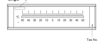
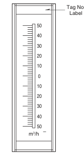
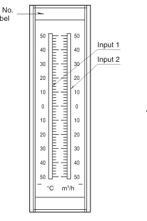
Label
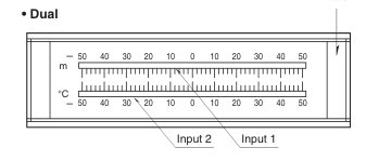
\*Engineering units longer than 3 characters are indicated here.
Remark: If there is only one engineering unit with dual bargraph type, the position and maximum number of characters for single bargraph type are applied.
CONNECTION DIAGRAM
■48V-2
■48V-1
+ 1
5 +
+ 1
5 +
INPUT 1
DC POWER
INPUT
DC POWER
– 2
6 –
– 2
6 –
+ 3
7 U
7 U
INPUT 2
AC POWER
AC POWER
– 4
8 V
8 V
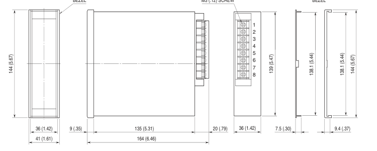
EXTERNAL DIMENSIONS & TERMINAL ASSIGNMENTS unit: mm (inch)
BEZEL
M3 (.12) SCREW
BEZEL
ES-9311 Rev.13 Page 4/5
Page 5
PANEL CUTOUT unit: mm
■ VERTICAL MOUNTING
Panel thickness: 1.6 – 5.5 mm
+1 L = (38 x n) –0 (n: number of units) L
Note 1. A bezel is required between units for high-density mounting. Note 2. Observe at the minimum of 5 cm above and below the units for heat dissipation.
■ HORIZONTAL MOUNTING
Panel thickness: 1.6 – 5.5 mm
+1
+1
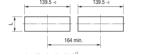
L = 38 x (n–1) + 36.5
–0
(n: number of units)
Note 1. A bezel is required between units for high-density mounting.
