
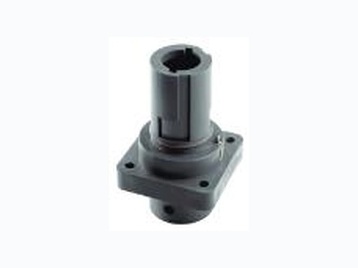
44420211 LAPP
Document overview
- Manufacturer or author: Provided By www.digicamel.com(free datasheet download site)
- PDF pages: 4
Technical content
44420211 DATA SHEET
Valid from:
21.10.2022 EPIC® POWERLOCK F6 C
Creator: STKU3/PDP Released: IVSE1/PDP Document: DB44420211EN Version: 04 Page 1 of 4 We reserve all rights according to DIN ISO 16016. PD 0019/05_04.18EN
Description
Single-pin circular connector for mobile power distribution, electro motors and generators Resistant to mechanical influences in harsh environmental conditions Connectors in harmonised colours according to European standards Every colour has a different coding to prevent incorrect plugging General Characteristics Series F6 C Version coupling connector, drain for crimp contact Rated voltage (V) 1000 V Rated impulse voltage 8 kV Rated current (A) max. crimp 660 A Contacts Crimp termination: copper, silver-plated Number of contacts 1 Termination methods Crimp termination: 35 - 240 mm² Protection IP 67 (maximum, dependant on cable gland used) IP 20 (unmated) Cycle of mechanical operation 500 Temperature range -25°C to +125°C Degree of soiling 3 Product Variations Article- Number Article M Pin configuration Type POWERLOCK F6, coupling connector , drain for crimp contact
44420211 POWERLOCK F6 PE/GN 40 PE, Green
44420212 POWERLOCK F6 N/BL 40 N, Blue
44420213 POWERLOCK F6 L1/BN 40 L1, Brown
44420214 POWERLOCK F6 L2/BK 40 L2, Black
44420215 POWERLOCK F6 L3/GY 40 L3, Grey
L1/red for direct current applications in conjunction with L2/black
44420318 POWERLOCK F6 L1/RD 40 L1, Red
VDE-Approval, VDE-REG.-No. D042
Valid from: Creator: STKU3/PDP Released: IVSE1/PDP Document: DB44420211EN Version: 04 Page 2 of 4 We reserve all rights according to DIN ISO 16016. PD 0019/05_04.18EN Technical Drawings
Valid from: Creator: STKU3/PDP Released: IVSE1/PDP Document: DB44420211EN Version: 04 Page 3 of 4 We reserve all rights according to DIN ISO 16016. PD 0019/05_04.18EN System description Line connector Panel mount connector Crimp contact Screw contact Source D6 Drain F6 Step 1) Selection of housings: Step 2) Selection of SKINTOP® cable gland M40 for the housing (only cable connectors): e.g. 3111250 (black), 53111450 (light grey), 53111050 (silver grey) Step 3) Decision: 400 A / max. 120mm² -> Screw contacts 660 A / max. 240mm² -> Crimp contacts ! Screw and crimp contacts are not allowed to be mixed! Step 4) Selection of contacts: Crimp contacts 35 mm² 50 mm² 70 mm² 95 mm² 120 mm² 150 mm² 185 mm² 240 mm² (NEW) Quelle (Source) 44420290 44420291 44420292 44420236 44420238 44420257 44420239 44420324 Senke (Drain) 44420293 44420294 44420295 44420231 44420233 44420256 44420234 44420339 Attention: The effective copper cross-sections of cables are significantly smaller than the electrical values given. We always recommend qualifying the cable-contact combination. (From 120 mm² strong effects on the quality of the connection. Example: 240 mm² cables fit better in 185 mm² contacts.) Contacts with M12 thread (for cable lug Ø12 mm) M12-thread 660 A M12-thread 400 A Source 44420261 44420242 Drain 44420260 44420241 Tightening torque M12 nut: 27,5 Nm - 31,4 Nm Generator (source) Electrical consumer (drain)
Valid from: Creator: STKU3/PDP Released: IVSE1/PDP Document: DB44420211EN Version: 04 Page 4 of 4 We reserve all rights according to DIN ISO 16016. PD 0019/05_04.18EN Robust Reliability Waterproof Info Connector for unscreened single-core power cables Application range For renewable energy plants e.g. wind power For mobile and stationary power distribution For the connection of motors, transformers and generators Light & sound technology Product features Straight connector with M40 thread Order SKINTOP® ST-M 40 or STR-M 40 separately Contact fixing by contact retention pin, each pin can only be used once Housing without contact, order contact separately Remark Photographs are not to scale and do not represent detailed images of the respective products.