

 Download PDF
442 CTS
Document overview
- PDF pages: 2
Technical content
Page 1

®
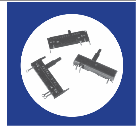
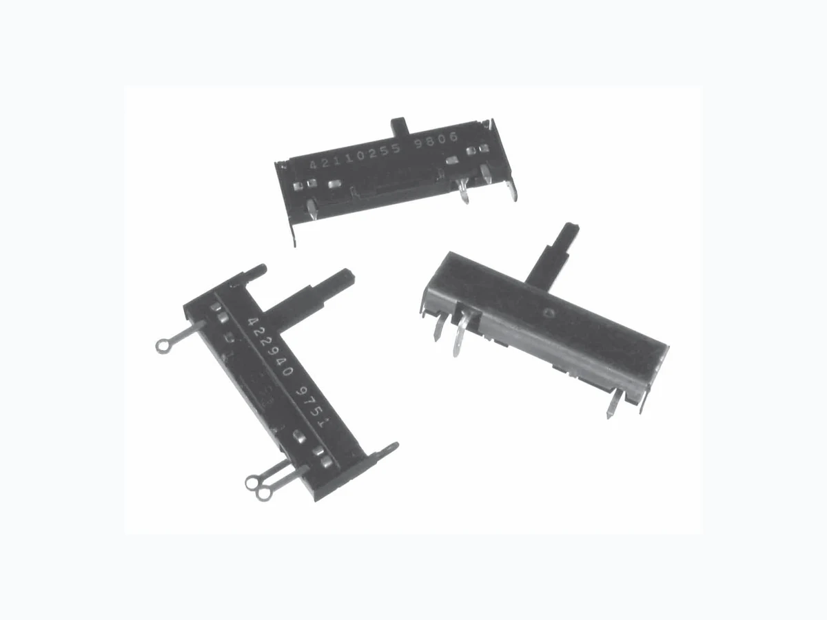
Linear Motion
1/4 Watt
Composition
Slide Controls
Features
- 11/4" (31.7mm) slider travel
- 1/4 watt power rating
- Choice of resistance tapers
- Economical
- Wide resistance range
- Choice of mounting styles
- RoHS compliant
Electrical and Mechanical Specifications
Resistance Range 200 ohms through 5 megaohms
Resistance Tolerance Standard: ±20% Available: ±10%
Power Rating, Watts 1/4 watt @ 55°C derated to no load @ 85°C, linear taper, control mounted on steel panel 4" x 4" x .050" (101.6mm x 101.6mm x 1.27mm).
Voltage Rating Across end terminals: Linear curves — 500 VDC Tapered curves — 350 VDC (Not to exceed wattage ratings) Between case and end terminals: 1080 VAC RMS
Resistance Tapers Standard: Linear Special: Available upon request
Operating Temperature 0°C - +70°C
Slide Travel Mechanical — 11/4 inches (31.7mm) Effective — 11/4 inches (31.7mm)
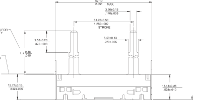
Shaft Information See illustrations, page 2.
Operating Force Either direction 1 to 9 in-oz. (28 to 256 gf-cm) Measured .250" (6.35mm) from base of slider.
Stop Strength Maximum — 35 in-lbs. (15.9 kg-cm) measured at base of slider.
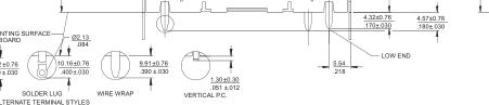
Terminal Information Straight, vertical or snap-in to printed circuit board, wirewrap or solder lug styles.
Mounting Information Top, bottom, side or no twist tab mounting — refer to illustrations, page 2.
© 2006 CTS Corporati on. All ri ghts reserved. Informati on subject to change.
1 - 2
9/21/06
CTS Electronic Components
www.ctscorp.com
Page 2
CTS Series 442
3.96±0.13
| 2.36±0.13 .093±.005 | .156±.005 3.96 .156 BOTTOM MOUNTING SURFACE 6.76 8.33 .266 .328 |
| 5.54±0.13 .218±.005 88 22 15.34 .604 3.96 ±0.13 .156 ±.005 | |
| 5.54±0.13 .218±.005 7.2 | 5.54±0.13 .218±.005 3.96±0.13 .156±.005 1.98 9 .078 |
CHECK CTS FOR AVAILABILITY
NO MOUNT CONSTRUCTION
20.88 .822
P.C. BOARD
4.32 .170
STRAIGHT P.C.
3.18
1.42
.125
.056
4.17
4.17
.164
.164
6.83
38.1
.269
1.500
51.77 2.038
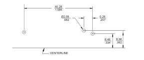
SUGGESTED PANEL PIERCING VIEWED FROM TOP SIDE FOR TWIST TABS AND ACTUATOR
VERTICAL P.C.
.287 SIDE MOUNTING 11.15 SURFACE .439
1.42 .056
51.77 2.038
SUGGESTED PANEL PIERCING VIEWED FROM TOP SIDE FOR TWIST TABS
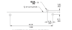
Ø2.08 (3)
| .082 (3) CL OF ACTUATOR | |
| 5.16 .203 40.28 | |
2.06 .081
2.54 .100
1.586
SUGGESTED PANEL PIERCING VIEWED FROM
SUGGESTED PANEL PIERCING VIEWED FROM
CONTROL SIDE FOR STRAIGHT P.C. & WIREWRAP TERMINALS
CONTROL SIDE FOR SNAP-IN P.C. TERMINALS
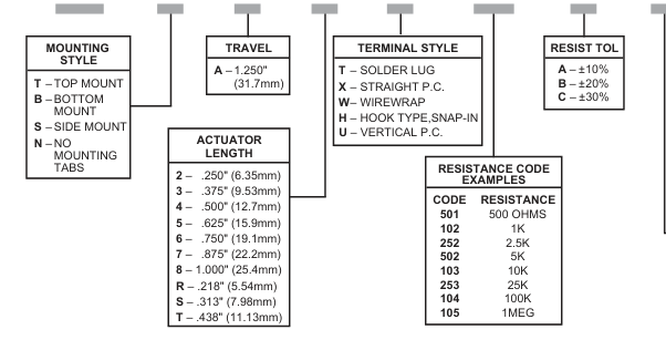
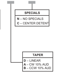
Ordering Information
442 T A 2 T
SUGGESTED PANEL PIERCING VIEWED FROM CENTERLINE OF CONTROL FOR VERTICAL P.C. TERMINALS
mm
DIMENSION:
INCH
103 B D N
© 2006 CTS Corporati on. All ri ghts reserved. Informati on subject to change.
2 - 2
9/21/06