

 Download PDF
T15 ALLEN-BRADLEY
Document overview
- PDF pages: 4
Technical content
Page 1
Description
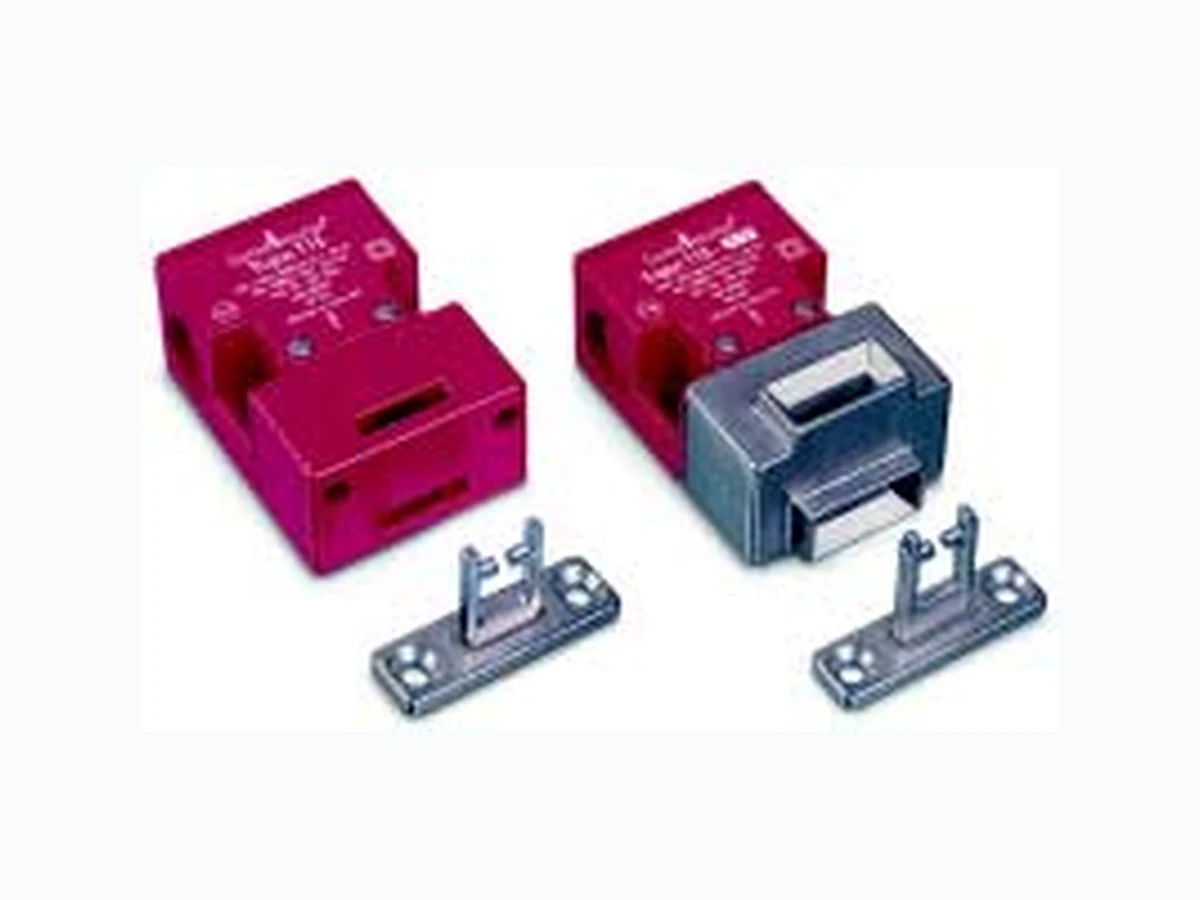
The Trojan T15 is a compact universal tongue actuated safety interlock switch designed to fit at the opening edge of sliding, hinged or lift-off guards. With its dual entry slots and rotatable head, movable only by releasing the cover screws, the Trojan T15 can offer four different options for actuator entry.
The Trojan T15 features a compact housing, only 75 x 52 x 32mm (2.95 x 2.04 x 1.25in) and includes direct opening action contacts and a tamper-resistant mechanism. The Trojan T15 has 2 N.C. safety contacts or 1 N.C. safety contact and 1 N.O. auxiliary contact. The unit is sealed to IP67 and has three M20 conduit entries.
Operation of the switch is achieved by the insertion of the specially profiled stainless steel actuator which should be permanently fixed to the leading edge of the guard door. The standard T15 incorporates actuator retention force of 30N. An optional catch mechanism helps keep doors shut on vibrating machinery.
Features
- Compact size, 75 x 52 x 32mm (2.95 x 2.05 x 1.26in) case
- 30N actuator retention force
- Strong and versatile, can be used in most applications
- Contacts: 2 N.C. safety or 1 N.C. safety & 1 N.O. auxiliary
- GD2 style available for demanding applications
Applications
Specifications
| Standards | EN954-1, ISO13849-1, IEC/EN60204-1, NFPA79, EN1088, ISO14119, IEC/ EN60947-5-1, ANSI B11.19, AS4024.1 |
| Category | Cat. 1 Device per EN954-1 Dual channel interlocks suitable for Cat. 3 or 4 systems |
| Approvals | CE marked for all applicable directives, cULus and TUV Nord |
| Safety Contacts | 2 N.C. or 1 N.C. direct opening action |
| Designation/Utilization Cat. A600/AC-15 (Ue) (Ie) N600/DC-13 (Ue) (Ie) | 600V 500V 240V 120V 1.2A 1.4A 3A 6A 600V 500V 250V 125V 0.4A 0.55A 1.1A 2.2A |
| Max. Switched Current/ Voltage/Load | 500V/500VA |
| Thermal Current (lth) | 10A |
| Min Current | 5V 5mA DC |
| Safety Contact Gap | >2 x 2mm (0.078in) |
| Rtd. Insulation Voltage | (Ui) 500V |
| Rtd. Impulse Withstand Volt. | (Uimp) 2500V |
| Auxiliary Contacts | 1 N.O. |
| Pollution Degree ➊ | 3 |
| Actuator Travel for Positive Opening | 6mm (0.236in) |
| Min Operating Radius | 175mm (6.89in) 60mm (2.36in) with flexible actuator |
| Break Contact Min Force | 30N (6.7lb) |
| Max Actuation Speed | 160mm (6.29) per sec |
| Max Actuation Frequency | 2 Cycle per sec |
| Case Material | UL approved glass filled polybutylene terephthalate |
| Actuator Material | Stainless Steel |
| Protection | IP67 |
| Conduit Entry | 3 x M20 or quick disconnect style |
| Operating Temperature | -20°C to +80°C (-4°F to +176°F) |
| Fixing | 2 x M5 |
| Mounting | Any position |
| Mechanical Life | 1,000,000 operations |
| Electrical Life | 1,000,000 operations |
| Weight | 120g (0.265lbs) |
| Colour | Red |
➊ Conductive pollution occurs, or dry, non conductive pollution occur which becomes conductive due to condensation.

Note: Lift-off guards require good alignment when using tongue actuated interlock switches. IMPORTANT: It must not be possible to lift the guard without actuating the interlock. An interlock on either side may be required.
3-10
Page 2
Product Selection
| Model Type | Contacts | Actuator | M20 Conduit | Quick Disconnect | ||
|---|---|---|---|---|---|---|
| Safety | Aux. | Standard | 1/2in NPT Adaptor | End Entry | ||
| Standard | 2 N.C. | — | Standard | 440K-T11303 | 440K-T11267 | 440K-T11307 |
| Fully-Flex | 440K-T11395 | 440K-T11273 | 440K-T11384 | |||
| — | 440K-T11269 | — | 440K-T11385 | |||
| 1 N.C. | 1 N.O. | Standard | 440K-T11305 | 440K-T11268 | 440K-T11386 | |
| Fully-Flex | 440K-T11396 | 440K-T11276 | 440K-T11387 | |||
| — | 440K-T11270 | — | 440K-T11388 | |||
| GD2 Front Entry | 2 N.C. | — | Standard | 440K-T11463 | 440K-T11288 | 440K-T11389 |
| Fully-Flex | 440K-T11397 | 440K-T11287 | 440K-T11390 | |||
| — | 440K-T11280 | — | 440K-T11391 | |||
| 1 N.C. | 1 N.O. | Standard | 440K-T11398 | 440K-T11284 | 440K-T11392 | |
| Fully-Flex | 440K-T11399 | 440K-T11283 | 440K-T11393 | |||
| — | 440K-T11279 | — | 440K-T11394 | |||
| Recommended mating cable, 2m (6.5ft). See page 15-10 for details and additional lengths. | 889D-F4AC-2 | |||||
Accessories
| Description | For Dimensions See Page | Catalogue Number | |
|---|---|---|---|
| Standard Actuator (Standard model only) | 14-5 | 440K-A11238 | |
| GD2 Standard Actuator (GD2 model only) | 14-4 | 440G-A27011 | |
| Flat Actuator | 14-5 | 440K-A11112 | |
3-11
Page 3
Accessories (continued)
| Description | For Dimensions refer to page | Catalogue Number | |
|---|---|---|---|
| Alignment Guide with Semi-Flexible Actuator (Discard the Alignment Guide for GD2) | 14-5 | 440K-A11144 | |
| Alignment Guide with Fully-Flexible Actuator (Discard the Alignment Guide for GD2) | 14-6 | 440K-A27010 | |
| Sliding Bolt Actuator | 14-4 | 440G-A27163 | |
| Catch and Retainer Kit (Standard Model Only) | 14-4 | 440K-A11094 | |
Optional Items
Catch and Retainer
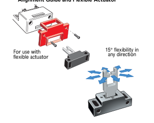
Alignment Guide and Flexible Actuator
Plug In Connection
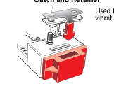
Used to keep guards on vibrating machinery closed.
The quick-disconnect option allows a quick connection facility.
3-12
Page 4
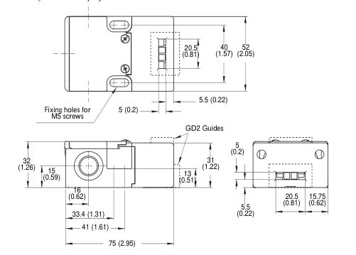
Approximate Dimensions—mm (inches)
Dimensions are not intended to be used for installation purposes.
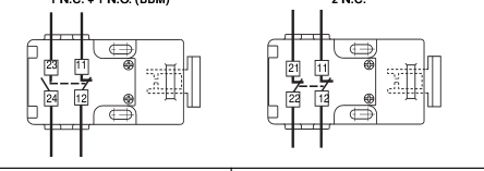
Typical Wiring Diagrams (shown with guard closed, actuator inserted)
2 N.C.
1 N.C. + 1 N.O. (BBM)

Contact Action
2 N.C.
1 N.C. & 1 N.O. (BBM)
Contact Open Contact Closed
20 15 10 6
20 15 10 6
0mm
0mm
11/12
11/12
Actuator withdrawal distance
23/24
21/22
from full insertion
6.5
3-13