
440 LITTELFUSE
Document overview
- Manufacturer or author: Provided By www.digicamel.com(FREE DATASHEET DOWNLOAD SITE)
- PDF pages: 4
Technical content
Features
Electrical Characteristics for Series t 0QFSBUJOH5FNQFSBUVSF from -55ºC to +150ºC t -FBEGSFF 3P)4 compliant and Halogen- free t 4VJUBCMFGPSCPUIMFBEFE and lead-free reflow / wave soldering t 6MUSBIJHI* 2t values % of Ampere Rating Ampere Rating Opening Time at 25ºC 100% 1 .75A - 8A 4 hours, Minimum 350% 1 .75A - 8A 5 secs., Maximum
Applications
(A) Amp Code Max. Voltage Rating (V) Interrupting Rating (AC/DC)1 Nominal Resistance (Ohms)2 Nominal Melting I2t (A2Sec.)3 Nominal Voltage Drop At Rated Current (V)4 Nominal Power Dissipation At Rated Current (W) Agency Approvals 1 .75 1 .75 32
50 A @ 32 V AC/DC
0.04121 0.3312 0.07769 0.136 x x Electrical Specifications by Item Notes: 1 . AC Interrupting Rating tested at rated voltage with unity power factor. DC Interrupting Rating tested at rated voltage with time constant < 0.8 msec. 2. Nominal Resistance measured with < 10% rated current. 3. Nominal Melting I²t measured at 1 msec. opening time. 4. Nominal Voltage Drop measured at rated current after temperature has stabilized. t "VUPNPUJWF&MFDUSPOJDT t -$%%JTQMBZT t 4FSWFST t /PUFCPPL$PNQVUFST t 1SJOUFST t 4DBOOFST t %BUB.PEFNT t )BSE%JTL%SJWFT Devices designed to carry rated current for 4 hours minimum. It is recommended that devices be operated continuously at no more than 80% rated current. See “Temperature Derating Curve”for additional derating information. Devices designed to be mounted with marking code facing up. Revised: September 17, 2009
Introduction to Circuit ProtectionIntroduction to Circuit Protection Transientology © 2009 Littelfuse, Inc. Specifications are subject to change without notice. Surface Mount Fuses Please refer to www.littelfuse.com/series/440.html for current information.
440 Series
Ceramic Fuse > 440 Series Average Time Current Curves 1.75A 2.5A 3.5A 0.001 0.01 0.1 TIME IN SECONDS 1 10 100 1000 CURRENT IN AMPERES Reflow Condition 1CGSFFBTTFNCMZ Pre Heat - Temperature Min (Ts(min)) 150°C - Temperature Max (Ts(max)) 200°C - Time (Min to Max) (ts) 60 – 180 seconds Average Ramp-Up Rate (Liquidus Temp (TL) to peak) 3°C/second max. TS(max) to TL - Ramp-up Rate 5°C/second max. Reflow - Temperature (TL) (Liquidus) 217°C - Temperature (tL) 60 – 150 seconds Peak Temperature (TP) 260+0/-5 °C Time within 5°C of actual peak Temperature (tp) 10 – 30 seconds Ramp-down Rate 6°C/second max. Time 25°C to peak Temperature (TP) 8 minutes max. Do not exceed 260°C Soldering Parameters T emperature Derating Curve 100 120 140 -65 -45 -25 -5 15 35 55 75 95 115 135 155 TEMPERATURE (°C) PERCENT OF RATING Time Temperature TP TL TS(max) TS(min) tP tL tS time to peak temperature (t 25ºC to peak) Ramp-down Ramp-up Preheat Critical Zone TL to TP &YBNQMF For continuous operation at 75 degrees celsius, the fuse should be derated as follows: I = (0.80)(0.85)I RAT = (0.68)IRAT Note: 1 . Derating depicted in this curve is in addition to the standard derating of 20% for continuous operation. Wave Soldering 260°C, 10 seconds max.
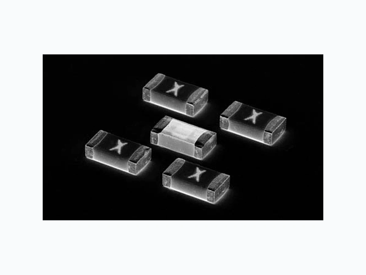
© 2009 Littelfuse, Inc. Specifications are subject to change without notice. Surface Mount Fuses Please refer to www.littelfuse.com/series/440.html for current information. Ceramic Fuse > 440 Series Body: Advanced Ceramic T erminations: Ag / Ni / Sn (100% Lead-free) Element Cover Coating: Lead-free Glass Moisture Sensitivity Level *1$+&%&$+45%$ -FWFM $POEJUJPO$ Humidity T est .*-45% .FUIPE# $POEJUJPOT% ESD Immunity *&$ L7%JSFDU Resistance to Solder Heat .*-45% .FUIPE' $POEJUJPO# Product Characteristics Moisture Resistance MIL -STD-202, Method 106G Thermal Shock MIL -STD-202, Method 107G, $POEJUJPO# Mechanical Shock .*-45% .FUIPE# Condition A Vibration MIL -STD-202, Method 201A Vibration, High Frequency MIL -STD-202, Method 204D, Condition D Dissolution of Metallization Condition D T erminal Strength *&$ Dimensions 3.200 ± .1778 [.126 ± .007] 1.000 [.039] X 1.500 [.059] 1.800 [.071] 3.500 [.138] 1.000 [.039] .8179 +.046/ -.076 0.520 ± .200 [.020 ± .008] TERMINATION 1.63 + .10/ -.20 Packaging Part Marking System Packaging Option Packaging Specification Quantity Quantity & Packaging Code QBSU 3000 WR Part Numbering System 0440 008. W R SERIES AMP CODE QUANTITY CODE W = 3000 pcs PACKING CODE 3FFM1BDL Amp Code Marking Code 1 .75 L 002. N 02.5 O 003. P 03.5 R 004. S 005. T 007 . W 008. X
Introduction to Circuit ProtectionIntroduction to Circuit Protection Transientology © 2009 Littelfuse, Inc. Specifications are subject to change without notice.