
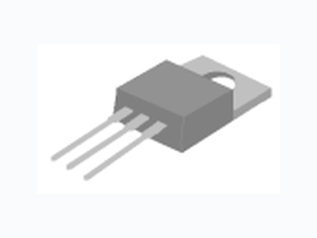
SSM40N03P ETC
Document overview
- Manufacturer or author: Provided By www.digicamel.com(FREE DATASHEET DOWNLOAD SITE)
- PDF pages: 6
Technical content
www.SiliconStandard.com 1 of 6 SSM 40N03P N-CHANNEL ENHANCEMENT-MODE POWER MOSFET Low gate charge BVDSS 30V Simple drive requirement R DS(ON) 17mΩ Fast switching ID 40A
Description
ID @ TC=25°C ID @ TC=100°C IDM A PD @ TC=25°C W/°C TSTG TJ Symbol Value Unit Rthj-c Thermal Resistance Junction-case Max. 2.5 °C/W Rthj-a Thermal Resistance Junction-ambient Max. 62 °C/W Parameter Rating Drain-Source Voltage 30 Gate-Source Voltage Continuous Drain Current, VGS @ 10V 40 A Continuous Drain Current, VGS @ 10V 30 A 0.4 Storage Temperature Range Total Power Dissipation 50 W -55 to 150 °C Thermal Data Parameter Pulsed Drain Current1 169 Operating Junction Temperature Range -55 to 150 °C Linear Derating Factor Power MOSFETs from Silicon Standard provide the designer with the best combination of fast switching, ruggedized device design, low on-resistance and cost-effectiveness. The TO-220 package is widely preferred for commercial and industrial applications and suited for low voltage applications such as DC/DC converters and high efficiency switching circuits. ± 20 G D S TO-220 G D S Rev.2.01 7/01/2004
www.SiliconStandard.com 2 of 6 SSM 40N03P Electrical Characteristics @ Tj=25oC (unless otherwise specified) Symbol Parameter Test Conditions Min. Typ. Max. Units BVDSS Drain-Source Breakdown Voltage V GS=0V, ID=250uA 30 - - V Δ BVDSS/ Δ Tj Breakdown Voltage Temperature Coefficient Reference to 25°C, ID=1mA - 0.037 -V/°C RDS(ON) Static Drain-Source On-Resistance VGS=10V, ID=20A - 14 17 mΩ VGS=4.5V, ID=16A - 20 23 mΩ VGS(th) Gate Threshold Voltage VDS=VGS, ID=250uA 1 - 3 V gfs Forward Transconductance VDS=10V, ID=20A - 26 - S IDSS Drain-Source Leakage Current (Tj=25oC) VDS=30V, VGS=0V - - 1 uA Drain-Source Leakage Current (Tj=150oC) VDS=24V,VGS=0V - - 25 uA IGSS Gate-Source Leakage VGS=- - nA Qg Total Gate Charge2 ID=20A - 17 - nC Qgs Gate-Source Charge VDS=24V - 3 - nC Qgd Gate-Drain ("Miller") Charge V GS=5V - 10 - nC td(on) Turn-on Delay Time2 VDS=15V - 7.2 - ns tr Rise Time ID=20A - 60 - ns td(off) Turn-off Delay Time RG=3.3Ω ,VGS=10V - 22.5 - ns tf Fall Time RD=0.75Ω -1 0- ns Ciss Input Capacitance VGS=0V - 800 - pF Coss Output Capacitance VDS=25V - 380 - pF Crss Reverse Transfer Capacitance f=1.0MHz - 133 - pF Source-Drain Diode Symbol Parameter Test Conditions Min. Typ. Max. Units IS Continuous Source Current ( Body Diode ) VD=VG=0V , VS=1.3V - - 40 A ISM Pulsed Source Current ( Body Diode )1 - - 169 A VSD Forward On Voltage2 Tj=25°C, IS=40A, VGS=0V - - 1.3 V Notes: 1.Pulse width limited by safe operating area. 2.Pulse width <300us , duty cycle <2%. ±100± 20V Rev.2.01 7/01/2004
www.SiliconStandard.com 3 of 6 SSM 40N03P Fig 1. Typical Output Characteristics Fig 2. Typical Output Characteristics Fig 3. On-Resistance v.s. Gate Voltage Fig 4. Normalized On-Resistance vs. Junction Temperature 0.60 0.80 1.00 1.20 1.40 1.60 1.80 -50 0 50 100 150 T j , Junction Temperature ( o C) Normalized RDS(ON) V G =10V I D =20A 100 150 0123456789 V DS , Drain-to-Source Voltage (V) ID , Drain Current (A) T C =25 o C V G =3.0V V G =4.0V V G =6.0V V G =8.0V V G =10V 100 150 0123456789 1 0 V DS , Drain-to-Source Voltage (V) ID , Drain Current (A) T C =150 o C V G =6.0V V G =3.0V V G =4.0V V G =8.0V V G =10V 3456789 1 0 1 1 V GS (V) RDSON (m ΩΩΩΩ) I D =20 A T C =25 o C Rev.2.01 7/01/2004
www.SiliconStandard.com 4 of 6 SSM 40N03P Fig 5. Maximum Drain Current vs. Fig 6. Typical Power Dissipation Case Temperature Fig 7. Maximum Safe Operating Area Fig 8. Effective Transient Thermal Impedance 25 50 75 100 125 150 T c , Case Temperature ( o C) ID , Drain Current (A) 100 1000 1 10 100 V DS (V) ID (A) T c =25 o C Single Pulse 10us 100us 1ms 10ms 100ms 0 50 100 150 T c ,Case Temperature ( o C) PD (W) 0.01 0.1 t , Pulse Width (s) Normalized Thermal Response (R thjc) PDM Duty factor = t/T Peak Tj = PDM x Rthjc + TC t T 0.02 0.01 0.05 0.1 0.2 DUTY=0.5 SINGLE PULSE Rev.2.01 7/01/2004
www.SiliconStandard.com 5 of 6 SSM 40N03P Fig 9. Gate Charge Characteristics Fig 10. Typical Capacitance Characteristics Fig 11. Forward Characteristic of Fig 12. Gate Threshold Voltage vs. Reverse Diode Junction Temperature -50 0 50 100 150 T j , Junction Temperature ( o C ) VGS(th) (V) 0 5 10 15 20 25 30 35 40 Q G , Total Gate Charge (nC) VGS , Gate to Source Voltage (V) V D =24V V D =20V V D =16V Id=20A 0.01 0.1 100 V SD (V) IS (A) T j = 25 o C T j = 150 o C 100 1000 10000 1 5 9 1 31 72 12 52 9 V DS (V) C (pF) f=1.0MHz Ciss Coss Crss Rev.2.01 7/01/2004
www.SiliconStandard.com 6 of 6 SSM 40N03P Information furnished by Silicon Standard Corporation is believed to be accurate and reliable. However, Silicon Standard Corporation makes no guarantee or warranty, expre ss or implied, as to the reliability, accuracy, timeliness or completeness of such information and assumes no responsibility for its use, or for infringement of any patent or other intellectual property rights of third parties that may result from its use. Silicon Standard reserves the right to make changes as it deems necessary to any products described herein for any reason, including without limitation enhancement in reliability, functionality or design. No license is granted, whether expressly or by implication, in relation to the use of any products described herein or to the use of any information provided herein, under any patent or other intellectual property rights of Silicon Standard Corporation or any third parties. Fig 13. Switching Time Circuit Fig 14. Switching Time Waveform Fig 15. Gate Charge Circuit Fig 16. Gate Charge Waveform td(on) tr td(off) tf VDS VGS 10% 90% Q VG QGS QGD QG Charge 0.5x RATED VDS TO THE OSCILLOSCOPE 10 V D G S VDS VGS RG RD 0.8 x RATED V DS TO THE OSCILLOSCOPE D G S VDS VGS IDIG 1~ 3 mA Rev.2.01 7/01/2004