
4063 ETC2
Document overview
- Manufacturer or author: Provided By www.digicamel.com(FREE DATASHEET DOWNLOAD SITE)
- PDF pages: 5
Technical content
D ual Channel Function/A rbitrary W aveform G enerators
4060 Series
w w w .bkprecision.com Technical data subject to change © B& K Precision Corp. 2015 Features & Benefits I 14-bit, 5 00 M Sa/s, 5 12k point (C h2 only) arbitrary waveform generator I Two independent channels with one-button synchronization I G enerate sine waves up to 16 0 M H z I Large 4.3 -inch LC D color display I Linear and logarithm ic sweep I AM /D SB -AM /ASK /FM /FSK /PM /PW M m odulation functions I Variable D C offset I Adjustable duty cycle I Internal/external triggering I G ate and burst m ode I 3 6 built-in predefined arbitrary waveform s I Store/recall up to 10 instrum ent settings and 3 2 user-defined arbitrary waveform s (8 x 5 12 kpts, 24 x 16 kpts) I B uilt-in counter I U SB device port (U SB TM C -com pliant) and front panel U SB host port I G PIB connectivity with optional U SB -to-G PIB adapter I Arbitrary waveform editing software included I Short circuit output protection I LabVIEW ™ drivers available The 406 0 Series D ual C hannel Function/Arbitrary W aveform G enerators are capable of generating stable and precise sine, square, triangle, pulse, and arbitrary waveform s. W ith an easy-to-read color display and intuitive user interface with num eric keypad, these instrum ents offer plenty of features including linear/logarithm ic sweep, built-in counter, extensive m odulation and triggering capabilities, a continuously variable D C offset, and a high perform ance 14-bit, 5 00 M Sa/s arbitrary waveform generator. Easily create custom arbitrary waveform s using the included waveform editing software or use any of the 3 6 built-in predefined arbitrary waveform s. U p to 8 user-defined 5 12-kpt arbitrary waveform s and 24 user-defined 16 -kpt arbitrary waveform s can be saved to the instrum ent. Additionally, the included LabVIEW ™ drivers allow users to conveniently load and save .C SV or text file data directly into the arb m em ory without having to use waveform editing software. M odel 4063 4064 4065 Sine frequency range 1 µH z – 8 0 M H z 1 µH z – 120 M H z 1 µH z – 16 0 M H z Square frequency range 1 µH z – 40 M H z 1 µH z – 5 0 M H z Extensive m odulation capabilities include am plitude and frequency m odulation (AM /FM ), double sideband am plitude m odulation (D SB - AM ), am plitude and frequency shift keying (ASK /FSK ), phase m odulation (PM ), and pulse width m odulation (PW M ). The standard external 10 M H z reference clock input and output allows users to synchronize their instrum ent with another generator. This feature is typically not found in function generators at this price point. Additionally, the phase of both output channels can be synchronized conveniently with the push of a button. These versatile function/arbitrary waveform generators are suitable for education and other applications that require high signal fidelity, a variety of m odulation schem es, or arbitrary waveform generation capabilities.
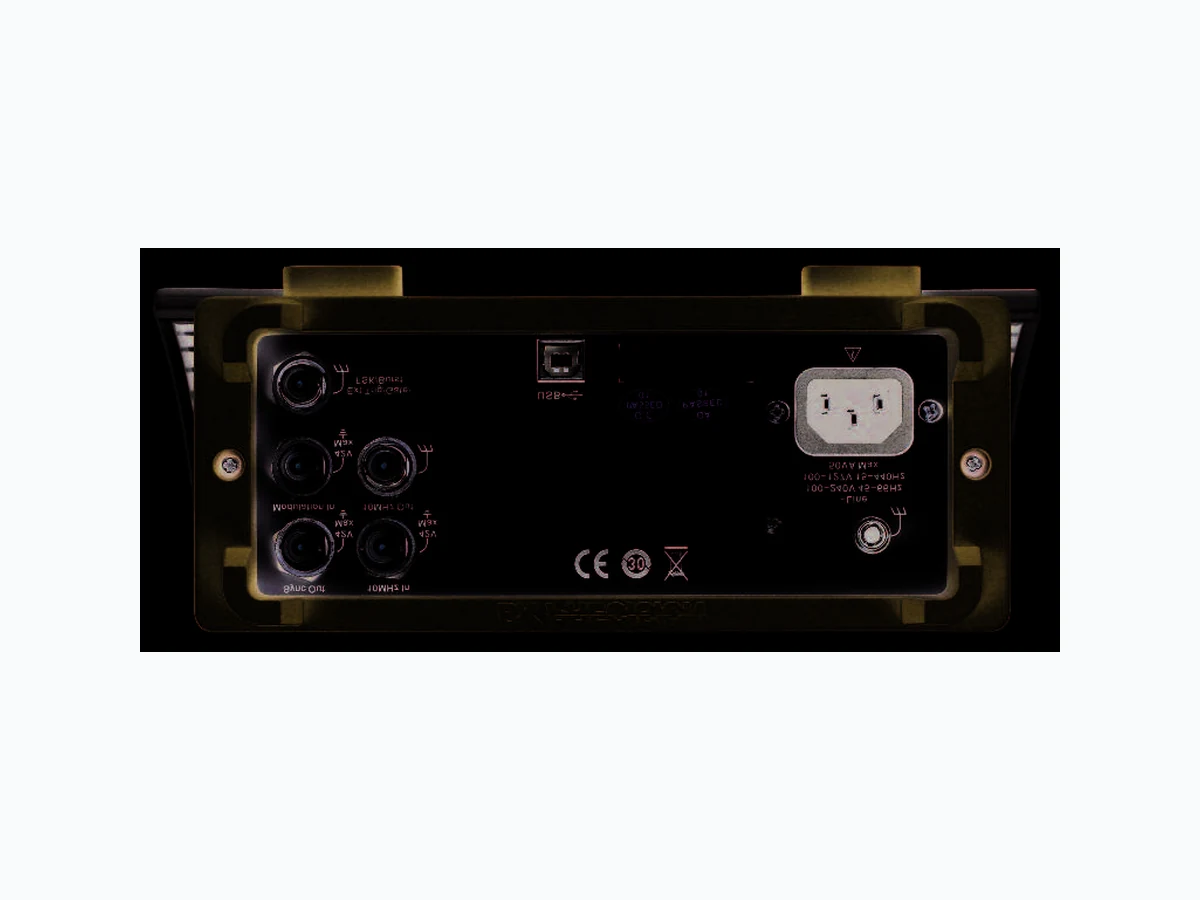
w w w .bkprecision.com D ual Channel Function/A rbitrary W aveform G enerators 4.3 ” color LC D display Front panel Rear panel D edicated channel selection buttons N um eric keypad Rotary control knob External 10 M H z clock input B N C Sync output B N C C hassis ground M odulation input B N C External trigger/gate/FSK /B urst B N C connector External 10 M H z clock output B N C U SB interface M enu function keys Power button W aveform s, U tility and Param eter keys M odulation, Sweep, and B urst keys C hannel outputs Intuitive user interface Easily adjust all waveform param eters using the intuitive m enu-driven front panel keypad with dedicated channel selection keys, num eric keypad, and rotary control knob. C onnect your U SB flash drive to the U SB host port to quickly save and recall instrum ent settings and waveform s. U SB host port
w w w .bkprecision.com D ual Channel Function/A rbitrary W aveform G enerators Easy-to-read color display Large 4.3 ” color display shows the currently selected channel and all relevant param eters. G enerate w aveform s w ith ease The provided waveform editing software can be used to create point-by-point arbitrary waveform s via freehand or waveform m ath functions. A standard U SB interface on the rear panel allows users to easily interface with a PC to load these arbitrary waveform s into the instrum ent. The front panel also offers a convenient U SB host port for connecting your U SB flash drive to save/recall instrum ent settings and waveform s. A rbitrary w aveform generation All m odels in the 406 0 series provide non-volatile m em ory to create, store, and recall up to 24 different 16 -kpt arbitrary waveform s and up to 8 different 5 12-kpt arbitrary waveform s. U sers can also output any of the 3 6 built-in predefined arbitrary waveform s. W ide variety of m odulation schem es These instrum ents are capable of m any different types of m odulation for various applications. M odulate your waveform s with AM , D SB -AM , FM , PM , ASK , FSK , and PW M m odulation schem es. D ual channel output Save tim e with the 406 0 Series’ two independent channels to output synchronous signals. W ith a push of a button, all waveform param eters can be quickly copied between channels to set up identical output signals. Phase between channels can also be adjusted from the front panel. Synchronization and external triggering U se the external 10 M H z clock input and output to synchronize your signals to a m aster tim e base. The Sync output generates a TTL pulse for synchronization to a channel’s frequency. An external trigger B N C connector is also available for inputting or generating a trigger signal. For applications requiring high signal integrity and edge stability, the 406 0 Series can generate pulses with a low cycle-to-cycle jitter of < 100 ps. Typical D D S generator with lim ited rise/fall tim e ranges 12 ns width pulse at 0.1 H z frequency U nlike traditional D D S generators, the 406 0 Series has the capability to output a rapid pulse at very low frequencies. D uty cycle can be set to as low as 0.0001%. A dvanced pulse generator 406 0 Series adjustable rise/fall tim es 8 6 .06 ps cycle-to-cycle jitter C apable of setting edge tim es within a large range, the 406 0 Series can generate pulses with m inim um rise/fall tim es of 6 ns and m axim um rise/fall tim es of 6 seconds. .
w w w .bkprecision.com D ual Channel Function/A rbitrary W aveform G enerators Accuracy ± 2 ppm (1 year) Resolution 1 µH z A rbitrary Characteristics B uilt-in W aveform s 3 6 W aveform Length C h1: 16 ,000 points, C h2: 5 12,000 or 16 ,000 points Vertical Resolution 14 bits Sam pling Rate 5 00 M Sa/s M inim um Rise/Fall Tim e 6 ns (typical) Jitter (pk-pk) 2 ns (typical) N on-volatile M em ory Storage 8 x 5 12 kpts waveform s and 24 x16 kpts waveform s O utput Characteristics Am plitude Range (into 5 0 Ω) 1 m Vpp – 10 Vpp, ≤ 40 M H z 1 m Vpp – 5 Vpp, ≤ 100 M H z 1 m Vpp – 1.5 Vpp, ≤ 16 0 M H z Am plitude Resolution up to 4 digits Am plitude Accuracy (100 kH z) ± (0.3 dB m + 1 m Vpp) Am plitude Flatness (relative to 100 kH z Sine, 1 Vpp) ≤ 10 M H z ± 0.2 dB ≤ 8 0 M H z ± 0.5 dB ≤ 16 0 M H z ± 0.8 dB C ross Talk < -6 5 dB c O ffset Range (D C ) ± 5 V into 5 0 Ω ± 10 V into open circuit O ffset Resolution up to 4 digits O ffset Accuracy ± ( |offset setting value| x 1% + 1 m V) O utput Im pedance 5 0 Ω, high im pedance O utput Protection short-circuit protection W aveform Characteristics H arm onic D istortion (Sine) D C – 1 M H z, < -5 4 dB c
1 M H z – 10 M H z, < -46 dB c
10 M H z – 100 M H z, < - 3 5 dB c
100 M H z – 16 0 M H z, < -26 dB c
T otal H arm onic D istortion (Sine) D C – 20 kH z at 1 Vpp, < 0.2 % Spurious (non-harm onic) D C – 1 M H z, < -70 dB c
1 M H z – 10 M H z, < -6 5 dB c
Phase N oise 100 kH z offset, - 116 dB c/H z (typical) Rise/Fall Tim e (Square) < 8 ns (10 % - 90 %) at full am plitude into 5 0 Ω Variable D uty C ycle (Square) 20% - 8 0% to 10 M H z 40% - 6 0% to 40 M H z 5 0% > 5 0 M H z Asym m etry (5 0% duty cycle) 1% of period + 5 ns (typical,1 kH z, 1 Vpp) Jitter (Square) 100 ps rm s (typical) Ram p Sym m etry 0% - 100% Linearity (Triangle, Ram p at 1 kH z, 1 Vpp, 100% Sym m etry) < 0.1% of peak output (typical) M odel 4063 4064 4065 C hannels 2 Frequency Characteristics Sine 1 µH z – 8 0 M H z 1 µH z – 120 M H z 1 µH z – 16 0 M H z Square 1 µH z – 40 M H z 1 µH z – 5 0 M H z Triangle, Ram p 1 µH z – 4 M H z Pulse 1 µH z – 20 M H z 1 µH z – 3 0 M H z 1 µH z – 40 M H z G aussian N oise (-3 dB ) 100 M H z Arbitrary 1 µH z – 20 M H z 1 µH z – 3 0 M H z 1 µH z – 40 M H z
W aveform s sine, square, ram p, arbitrary (except D C ) Sweep Shape linear or logarithm ic, up or down Sweep Tim e 1 m s – 5 00 s ± 0.1% Sweep Trigger internal, external, m anual Inputs and O utputs O utput Im pedance 5 0 Ω, high im pedance Sync O ut TTL com patible > 5 0 ns width, not adjustable 5 0 Ω (typical ) output im pedance 10 M H z m ax. frequency M odulation In ± 5 V for 100% m odulation > 10 k Ω input im pedance m ax. voltage input: + 5 V External C lock In Frequency Range: 10 M H z ± 1 kH z M in. Voltage Input: 2.3 V External C lock O ut Frequency: 10 M H z Voltage Level: > 1 Vpp Ext Trig/G ate/FSK /B urst TTL com patible m ax. voltage input: + 5 V Frequency Counter M easurem ent frequency, period, positive/negative pulse width, duty cycle M easurem ent Range 100 m H z – 200 M H z Frequency Resolution 6 bits Voltage Range (non-m odulated signal) D C C oupling D C offset range: ± 1.5 VD C 100 m H z – 100 M H z, 5 0 m Vrm s - ± 2.5 V 100 M H z – 200 M H z, 100 m Vrm s - ± 2.5 V AC C oupling 1 H z – 200 M H z, 100 m Vrm s – 5 Vpp Pulse W idth/D uty C ycle Voltage Range 5 0 m Vrm s – 5 Vpp Input Im pedance 1 M Ω C oupling AC , D C Trigger Level Range -3 V to + 1.8 V Environm ental and Safety T em perature operating: 3 2 ºF – 104 ºF (0 °C – 40 °C ) storage: -4 ºF – 140 ºF (-20 °C – 6 0 °C ) H um idity < 95 º F (< 3 5 °C ), ≤ 90 % RH 95 ºF – 104 ºF (3 5 °C – 40 °C ), ≤ 6 0 % RH Altitude operating: below 9,8 42 ft (3 ,000 m ) storage: below 49,212 ft (15 ,000 m ) Electrom agnetic C om patibility EM C D irective 2004/108 /EC , EN 6 13 26 :2006 , EN 6 1000-3 -2:2006 + A2:2009, EN 6 1000-3 -3 :2008 Safety low voltage directive 2006 /95 /EC , EN 6 1010-1:2001, EN 6 1010-03 1:2002+ A1:2008 G eneral D isplay 4.3 ” TFT -LC D display, 48 0 x 272 Interfaces U SB TM C (standard), G PIB (optional), U SB host port Storage M em ory 10 instrum ent settings, 3 2 arbitrary waveform s AC Input 100 – 240 VAC ± 10%, 5 0 / 6 0 H z ± 5 % 100 – 120 VAC ± 10%, 45 – 440 H z Power C onsum ption 3 0 W m ax. D im ensions (W x H x D ) 10.3 ” x 4.1” x 13 .5 ” (26 1 x 105 x 3 44 m m ) W eight 6 .1 lbs (2.8 kg) Three-Year W arranty Standard Accessories G etting started m anual, full instruction m anual on C D , AC power cord, U SB type A-to-type B cable, certificate of calibration O ptional Accessories U SB -to-G PIB adapter (m odel AK 40G ) v050515 5 w w w .bkprecision.com D ual Channel Function/A rbitrary W aveform G enerators M odel 4063, 4064 & 4065 Pulse Pulse W idth 12 ns m inim um , 100 ps resolution, 1,000,000 s m ax Rise/Fall Tim e 6 ns – 6 s (1) , 100 ps resolution D uty C ycle Range 0.0001 % to 99.9999 % O vershoot < 3 % Jitter (pk-pk) < 100 ps rm s (typical) Burst W aveform sine, square, ram p, pulse, arbitrary (except D C ) Type cycle (1 – 1,000,000 cycles), infinite, gated Start/Stop Phase 0 ° – 3 6 0 ° Internal Period 1 µs – 1000 s ± 1% G ated Source external trigger Trigger Source internal, external, m anual Phase O ffset Range -3 6 0 ° – 3 6 0 ° Resolution 0.1 ° Trigger Characteristics Trigger Input Input Level TTL com patible Slope rising or falling, selectable Pulse W idth > 5 0 ns Input Im pedance > 5 k Ω, D C coupling M axim um Frequency 1 M H z Input Latency < 3 8 0 ns Trigger O utput Voltage Level TTL com patible Pulse W idth > 6 0 ns (typical) O utput Im pedance 5 0 Ω (typical ) M axim um Frequency 1 M H z A M , FM & PM M odulation Characteristics C arrier sine, square, ram p, arbitrary (except D C ) Source internal, external M odulation W aveform sine, square, ram p, noise, arbitrary (1 m H z – 5 0 kH z) AM M odulation D epth 0% - 120%, 0.1% resolution FM Frequency D eviation 0 – 0.5 x bandwidth, 1 m H z resolution PM Phase D eviation 0 – 3 6 0 °, 0.1 ° resolution A SK & FSK M odulation Characteristics C arrier sine, square, ram p, arbitrary (except D C ) Source internal, external M odulation W aveform 5 0% duty cycle square waveform (1 m H z – 1 M H z) D SB-A M M odulation Characteristics C arrier sine, square, ram p, arbitrary (except D C ) Source internal, external M odulation W aveform sine, square, ram p, noise, arbitrary (1 m H z – 5 0 kH z) PW M M odulation Characteristics Source internal, external M odulation W aveform sine, square, ram p, arbitrary (except D C ) External M odulation - 5 V to + 5 V (m ax. width deviation) D uty C ycle M odulating Frequency 1 m H z – 5 0 kH z (1) depending on pulse width