
4014B ETC2
Document overview
- Manufacturer or author: Provided By www.digicamel.com(FREE DATASHEET DOWNLOAD SITE)
- PDF pages: 3
Technical content
D D S Sw eep Function G enerators M odels 4014B and 4040B D ata Sheet w w w .bkprecision.com Technical data subject to change © B& K Precision Corp. 2013 M odels 4014B and 4040B are 12 M Hz and
20 M Hz D D S (direct digital synthesis) function
generators that generate stable and precise sine, square, and triangle waveform s. B oth m odels provide variable output voltages from 0 to
10 Vpp into 5 0 Ω (up to 20 Vpp into open
circuit), linear and logarithm ic sweep, A M /FM m odulation, built-in counter, and a continuously variable D C offset that allows the output to be injected directly into circuits at the correct bias level. Separate output am plitude and D C offset am plifiers let you set a large D C offset (e.g. ± 4.99 V ) with a sm all am plitude output signal (e.g. 10 m V), a feature typically found in m ore expensive generators. The 4014B and 4040B are both designed with a dual technology architecture, com bining traditional D D S technology with a low-jitter square wave generator. The instrum ents generate a 2-point waveform to sim ulate the am plitude and use a high accuracy PLL (phase-locked loop) circuit for tim ing. C om pared to signals generated by typical low-cost D D S function and arbitrary waveform generators, this im plem entation significantly m inim izes jitter and im proves edge stability of square waves. The im proved signal integrity allows these generators to be used for sim ulating reliable clock signals, generating triggers, or validating serial data buses. These m odels are suitable for education and other applications that require digital function generators with sweep and m odulation capabilities. Features & Benefits I Sine and square waveform s up to
12 M Hz (4014B ) or 20 M Hz (4040B )
I Triangle/ram p waveform s up to
1 M Hz (4014B ) or 2 M Hz (4040B )
I B right color display with waveform preview I Linear and logarithm ic sweep I A M /FM m odulation I Independent output and D C offset am plifiers allow for sm all am plitude output signals with large D C offsets I Low-jitter square wave generation I A djustable duty cycle I O utput O N /O FF button I Internal/external triggering I G ate and burst m ode (4040B only) I B uilt-in counter I U SB interface I SC PI-com pliant com m and set I Short circuit and overvoltage protection on all inputs and outputs M odel 4014B 4040B Sine and square frequency range 0.01 Hz - 12 M Hz 0.01 Hz - 20 M Hz Triangle/ram p frequency range 0.01 Hz - 1 M Hz 0.01 Hz - 2 M Hz
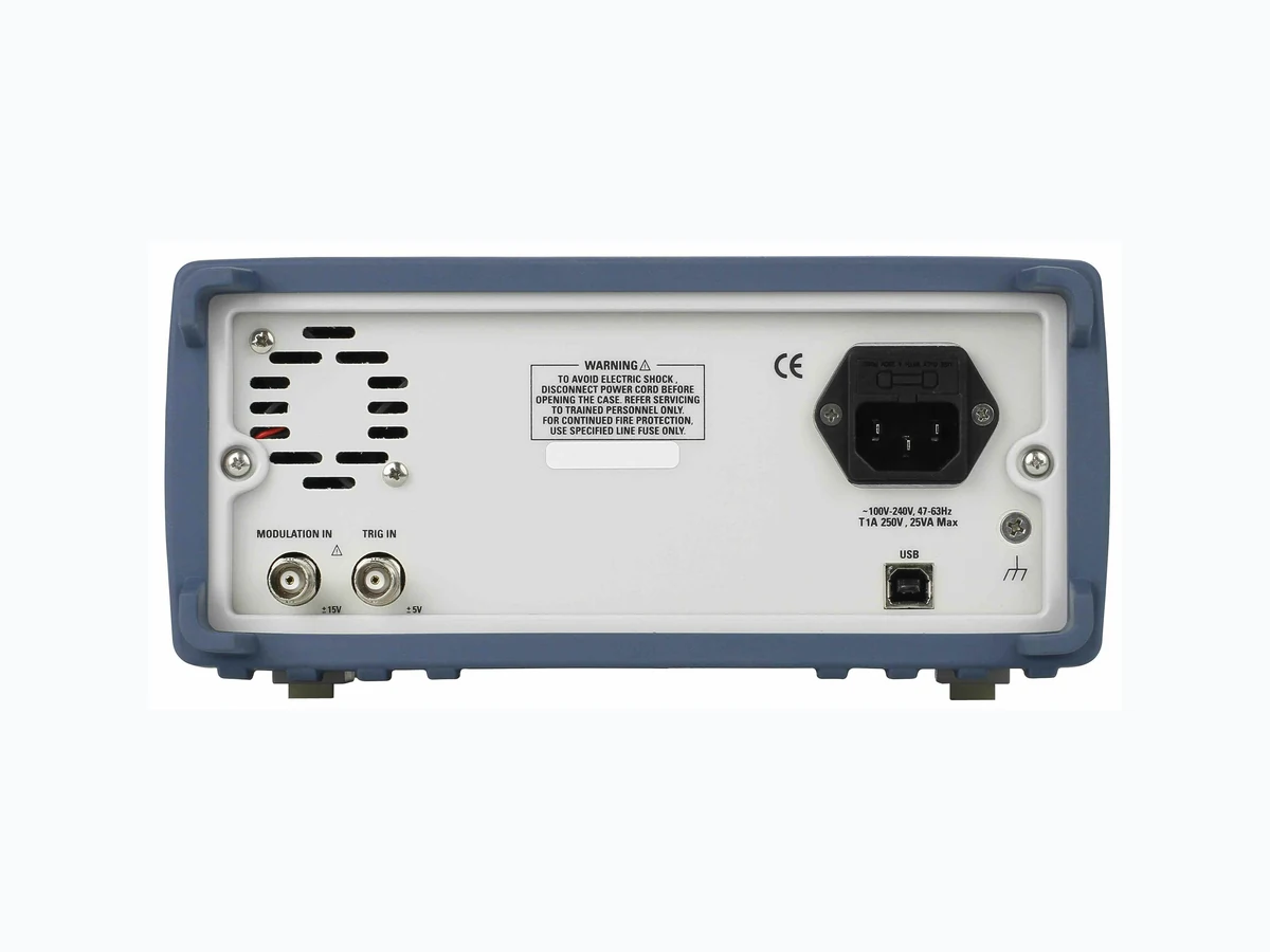
w w w .bkprecision.com D D S Function G enerators M odels 4014B and 4040B O utput O n/O ff button M ain output U SB interface M odulation input connector Trigger/counter input connector Rotary control knob C olor LC D display N um eric keypad D edicated waveform keys Lin/Log sweep key M odulation key U tility key Sync output Easily change all waveform param eters using the intuitive m enu-driven front panel keypad, rotary control knob, and large color LC D display that shows a preview of the output waveform . C onvenient waveform and range selection buttons let users m ake quick and precise adjustm ents to the output signal. Front panel Rear panel M enu function keys Intuitive user interface Versatile tools Easy PC connectivity The function generators can be program m ed rem otely via the U SB (virtual C O M ) interface using SC PI com m ands. B &K Precision also offers application software (available for download at www.bkprecision.com ) that provides virtual front panel em ulation, allowing users to rem otely control their instrum ent without the need for program m ing. B oth m odels provide A M and FM m odulation along with linear/logarithm ic sweep and built-in counter capabilities. Internal and external sources can be used for triggering and m odulating the signal.
w w w .bkprecision.com D D S Function G enerators M odels 4014B and 4040B * For square wave, resolution is up to 4 digits when frequency is > 20 kHz. N ote: A ll specifications apply to the unit after a tem perature stabilization tim e of 15 m inutes over an am bient tem perature range of 23 ºC ± 5 ºC . Specifications are subject to change without notice. v112713 Specifications 4014B 4040B Frequency Characteristics Sine 0.01 Hz to 12 M Hz 0.01 Hz to 20 M Hz Square 0.01 Hz to 12 M Hz 0.01 Hz to 20 M Hz Triangle 0.01 Hz to 1 M Hz 0.01 Hz to 2 M Hz Resolution 6 digits* or 10 m Hz A ccuracy 0.01% ± 0.006 Hz O utput Characteristics A m plitude Range 10 m Vpp to 10 Vpp (into 5 0 Ω); 20 m Vpp to 20 Vpp (open circuit) A m plitude Resolution 3 digits (1,000 counts) A m plitude A ccuracy ± 2% ± 20 m V of program m ed output from 1.01 V – 10 V Flatness ± 0.5 dB to 1 M Hz ± 1 dB to 12 M Hz ± 0.5 dB to 1 M Hz ± 1 dB to 20 M Hz D C O ffset Range -4.99 V to 4.99 V (into 5 0 Ω) D C O ffset Resolution 10 m V , 3 digits D C O ffset A ccuracy ± 2% ± 10 m V (into 5 0 Ω) O utput Im pedance 5 0 Ω ± 2% O utput Protection Protected against short circuit or accidental voltage applied to the m ain output connector W aveform Characteristics Harm onic D istortion (for sine wave at
5 Vp-p into 5 0 Ω)
0 – 1 M Hz, < -6 0 dB c
1 M Hz – 5 M Hz, < -5 0 dB c
5 M Hz – 12 M Hz, < -45 dB c
0 – 1 M Hz, < -6 0 dB c
12 M Hz – 20 M Hz, < -5 0 dB c
Square Rise/Fall Tim e ≤ 20 ns (10% to 90% at full am plitude into 5 0 Ω) D uty C ycle Square: 20% - 8 0% to 2 M Hz Triangle: 1% - 99% in 1% steps, up to 200 kHz Sym m etry A ccuracy at 5 0% ± 1% Jitter (square) < 100 ps rm s (cycle-to-cycle, typical) O perating M odes C ontinuous O utput continuous at program m ed param eters Triggered O utput quiescent until triggered by an internal or external trigger, at which tim e one waveform cycle is generated to program m ed param eters. Frequency of waveform cycle is lim ited to 1 M Hz. G ate - Sam e as triggered m ode, except waveform is executed for the duration of the gate signal. The last cycle started is com pleted. B urst - 2-6 5 5 3 5 cycles Trigger Source Trigger source m ay be internal, external, or m anual. Internal trigger rate 0.1 Hz – 1 M Hz (1 us – 10 s) M odulation Characteristics A m plitude M odulation Internal 0.1 Hz – 20 kHz sine only 0.1 Hz – 20 kHz sine, square, or triangle waveform External 5 Vp-p for 100% m odulation, 10 k Ω input im pedance Frequency M odulation Internal 0.1 Hz – 20 kHz sine only 0.1 Hz – 20 kHz sine, square, or triangle waveform External 5 Vp-p for 100% m odulation, 10 k Ω input im pedance Sw eep Characteristics Sweep Shape Linear or Logarithm ic, up or down Sweep Tim e 10 m s to 100 s Input and O utput Trigger IN TTL com patible M axim um rate 1 M Hz Input im pedance 1 k Ω M inim um width > 5 0 ns Sync O U T TTL pulse at program m ed frequency; 5 0 Ω source im pedance M odulation IN
5 Vp-p for 100% m odulation
10 k Ω input im pedance D C to > 20 kHz m inim um bandwidth Counter Characteristics Range 5 0 Hz to 25 M Hz Resolution A uto ranging, up to 8 digits A ccuracy ± 0.02% ± 2 digits Sensitivity 100 m Vrm s typical G eneral M em ory Storage 10 instrum ent settings 20 instrum ent settings Power Requirem ents 100 V – 240 V A C ± 10% O perating T em perature 3 2 °F to 122 °F (0 °C to 5 0 °C ) Storage T em perature 14 °F to 15 8 °F (-10 °C to 70 °C ) Hum idity 95 % R.H. 0 °C to 3 0 °C D im ensions (W x H x D ) 8 .3 9” x 3 .46 ” x 8 .27” (213 x 8 8 x 210 m m ) W eight 5 .5 lbs (2.5 kg) Electrom agnetic C om patibility M eets EM C D irective 2004/108 /EC , EN 5 5 011, EN 5 5 08 2 Safety M eets Low Voltage D irective 2006 /95 /EC , EN 6 1010 Three-Year W arranty Included A ccessories Instruction m anual on C D , power cord, U SB (type A to B ) interface cable, certificate of calibration