

 Download PDF
400-50T ANAREN
Document overview
- PDF pages: 2
Technical content
Page 1

Model RFP-400-50T
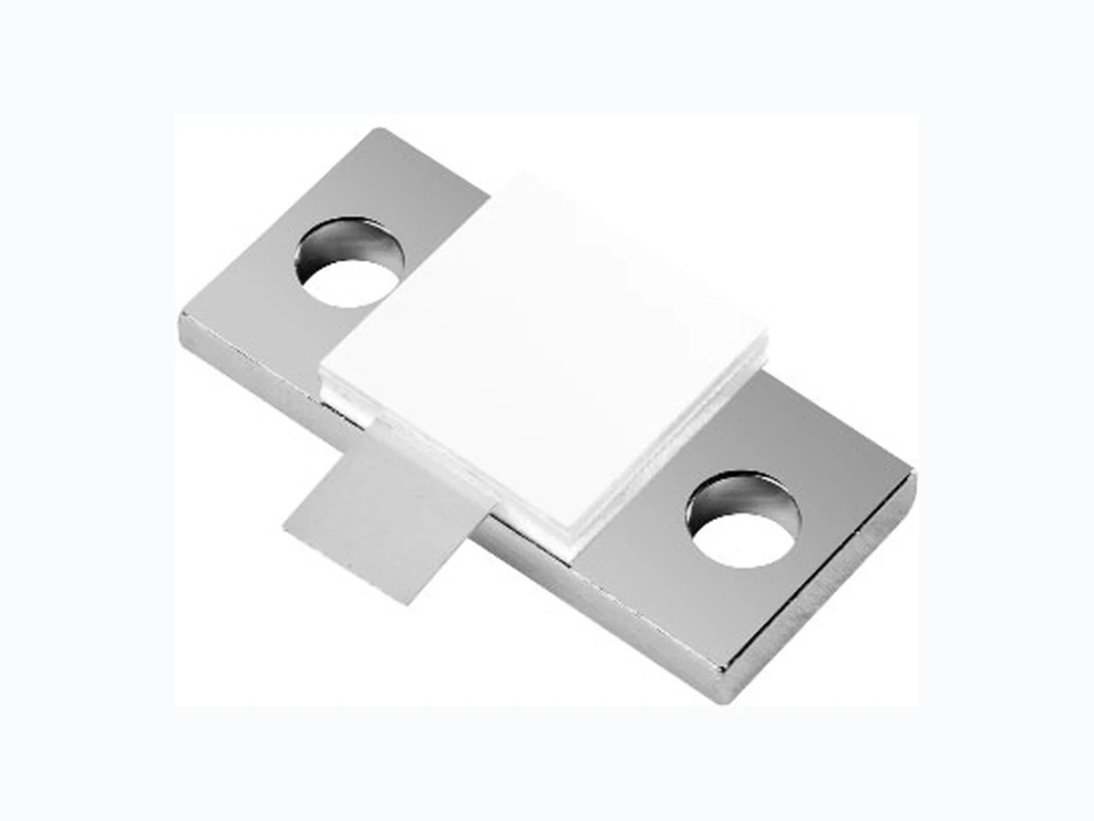
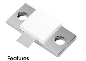
Flanged Terminations

400 Watts, 50 Ω
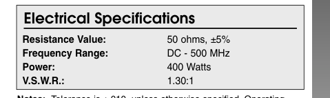
- DC - 500 MHz
- 400 Watts
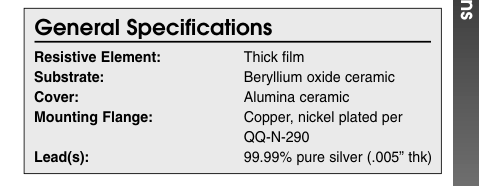
- BeO Ceramic
- Welded Silver Leads
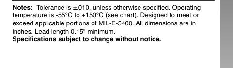
- Non-Nichrome Resistive
Element
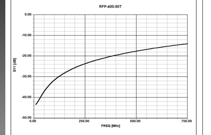
- Low VSWR
- 100% Tested
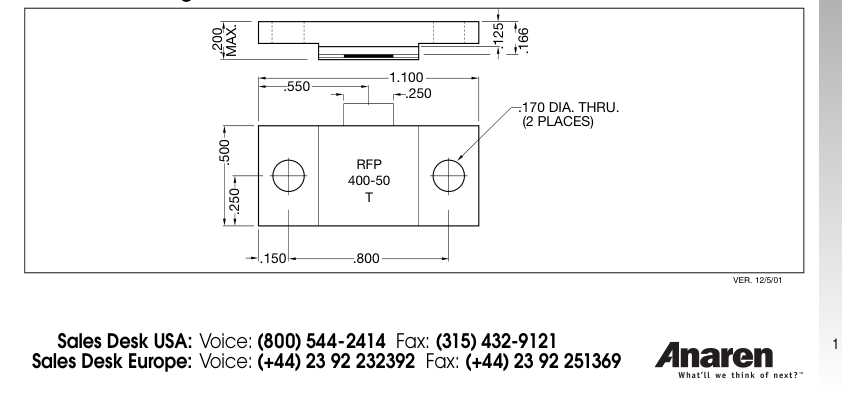
Outline Drawing
Page 2

Model RFP-400-50T

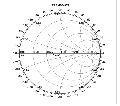
Typical Performance
Suggested Mounting Procedures
Power Derating
.025
100
75
50
25
0
25 50 75 100 125 150
CASE TEMPERATURE — °C
MIN. (2 PLACES)
BOARD LOWER
BOARD HIGHER
BOARD EVEN
BOARD LOWER
THAN LEAD.
THAN LEAD.
THAN LEAD.
WITH LEAD.
NOT RECOMMENDED APPLICATION
SUGGESTED STRESS RELIEF METHODS
SCALE:
SCALE:
- Make sure that the devices are mounted on flat surfaces (.001” under the device) to optimize the heat transfer. 2. Drill & tap the heatsink for the appropriate thread size to be used. 3. Coat heatsink with a minimum amount of high quality silicone grease (.001” max. thickness). 4. Position device on mounting surface and secure using socket head screws, flat & split washers. Torque screws to the appropriate value. Make sure that the device is flat against the heatsink. (Care should be taken to avoid upward pressure of the leads towards the lid). 5. Solder leads in place using an SN63 type solder with a controlled temperature iron (210°C).