
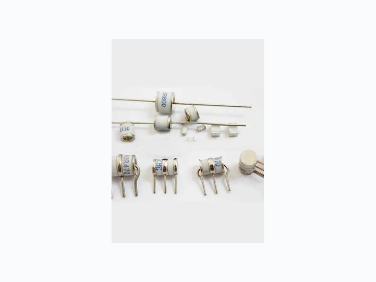
3R070B-6 LEIDITECH
Document overview
- Manufacturer or author: Provided By www.digicamel.com(FREE DATASHEET DOWNLOAD SITE)
- PDF pages: 5
Technical content
Features
Applications
- Broad voltage range from 75V-600V
- Various form factors: surface mount, axial leads, no leads
- Low capacitance and insertion loss
- RoHS compliant
- Devices tested per ITU K.12 recommendations
- Non-radioactive materials ROHS All data is subject to change,Please check our data sheets at www.leiditech.com for updates.
Electriacl Characteristics GDT 02 Type number DC Spark- over voltage Maimum Impulse spark-over voltage Impuise life 10/1000us,100A Minimum Insulation resistance Maximum Capacitance Maximum surge Discharge Current @8/20us,10times Altermationg Dischare Curiren V @100v/s V @1kv/us Times Test Voltage GΩ pF @1MHz KA A @50Hz 1S 300 times DC 25V 2.0 pF 5KA 5A 3R090(T,S,L,C)A-6 90±20% 750 DC 50V DC 100V DC 250V 3R075(T,S,L,C)B-6 75±20% 750 DC 25V 10KA 10A 3R090(T,S,L,C)B-6 90±20% 750 DC 50V DC 100V DC 250V Notes: 1.Insulation resistance measure at: DC 50V for the 3R075,3R090,and 3R150 DC 100V for other. 2. Terms in accordance with ITU-T K.12 and GB/T 9043-1008 3. At delivery AQL 0.65 level 2 DIN ISO 2859 All data is subject to change,Please check our data sheets at www.leiditech.com for updates.
Device TypeD escription Quantity Type S 100pcs/tray x 5 trays per carton5 00 Type T 100pcs/tray x 5 trays per carton5 00 Type L 100pcs/tray x 5 trays per carton5 00 Type C 50pcs/tray x 5 trays per carton 250 6.1 [0.240] 8.00 [0.318] 8.50 [0.338] 4.4± 0.3 [0.173± 0.12] 4.4± 0.3 [0.173± 0.12] [0.511] 4.4 [0.173] 1.0 DIA. MAX. [0.039] 11.5 ± 1 [0.456 ± 0.039] 6.1 [0.240] 6.35 ± 0.5 [0.25 ± 0.25] [0.511] 1.0 DIA. MAX. [0.039] 6.1 DIA. MAX. [0.240] [0.398] 12.7 [0.500] 6.35 ± 0.5 [0.25 ± 0.25] 8.10 [0.398] [0.787] 1.0 DIA. MAX. [0.039] 48 ± 3 [1.889 ± 0.118 ] 6.1 DIA. MAX. [0.240] Type T - Shaped Radial Leads Type L - Straight Radial Leads Type C - Straight "T" Leads Type S - Surface Mount Core NOTE: Failsafe option dimensions shown in green. 8.1 All data is subject to change,Please check our data sheets at www.leiditech.com for updates.
Pr oduct Cha ra ct er istics Materials Dull Tin Plate 17 .5 ± 1 2.5 Microns with Ceramic Insulator Pr oduct Mar king Lit telfuse ‘LF’ markin g, V olt age and date code. Glo w t o ar c tr ansition cu rr ent ~ 1Amp Gl ow V olta ge ~ 60-2 00 V olts Pb – F ree assembly P re Heat - T emperature Min (T s(min) )1 50°C - T emperature Max (T s(max) )2 0 0°C - T ime (Min to Max) (t s ) 60 – 1 80 secs A verage ramp up rate (Liquidus T emp L ) to peak 3°C/second max T S(max) to T L - R amp-up R ate 5°C/second max - T emperature (T L ) (Liquidus) 21 7°C - T emperature (t L ) 60 – 1 50 seconds P eak T emperature (T P ) 260 +0/-5 T ime within 5°C of actual peak T emperature (t p ) 1 0 – 30 seconds R amp-down R ate 6°C/second max T ime 25°C to peak T emperature (T P ) 8 minutes Max. Do not exceed 260°C Ti me erutarep meT T P T L T S(max) T S(min) t P t L t S time to peak temperature (t 25ºC to peak) Ramp-down Ramp-up Preheat Critical Zone T L to T P Solder ing Pa r amet ers - W av e Solder ing (Thr u-Hole Devices) Solder ing Pa r amet ers - Hand Solder ing Dwell T ime 100 120 14 0 160 180 200 220 24 0 260 280 300 10 0 11 0 12 0 13 0 14 0 15 0 16 0 17 0 18 0 19 0 20 0 21 0 22 0 23 0 24 0 T ime (Seconds) T emperature (°C) - Measured on bottom side o f boar d Cooling T imePreheat T ime W ave P aramete rL ead-F ree R ecommendation P reheat: (Depends on Flux A ctiv ation T emperat ure) (T ypical Indust ry R ecommendation) T emperat ure Minimum: 10 0 C T emperat ure Maximum: 15 0 C P reheat Time: 60-1 80 seconds S older P ot T emperature: 280 C Maximum S older Dwell T ime: 2-5 seconds Recommended Pr ocess P ar amet ers: Solder Iron T emperat ure: 350° C +/- 5°C Heating Time: 5 seconds max. Note: Surge A rrestors with a F ailsaf e mec hanism should be individually e xamined after soldering St or ag e and Oper ational Te mper at ur e -40 to +90°C Tr ansv erse V oltag e (Del ay T ime) T ested to I TU-T R ec. K. 12 < 0.2µSec Ar c V olta ge ~ 1 0 to 35 V olts Hold ov er V olta ge T ested to I TU-T R ec. K.1 2 & REA PE 80 < 1 50mS All data is subject to change,Please check our data sheets at www.leiditech.com for updates.
3 R 3 5 0 T B - 6
T=Clubfoot S=SMD L=Straight Dimensions Electrical Characteristics A=5000A B=10000A All data is subject to change,Please check our data sheets at www.leiditech.com for updates. Leiditech Electronics are trademarks. Information furnished is believed to be accurate and reliable. However, users should independently evaluate the suitability of and test each product selected for their own applications. Leiditech Electronics reserves the right to change or update, without notice, any information contained in this publication; to change, without notice, the design, construction, processing, or specification of any product; and to discontinue or limit production or distribution of any product. This publication supersedes and replaces all information previously supplied. Without expressed or written consent by an officer of Leiditech Electronics, Leiditech Electronics does not authorize the use of any of its products as components in nuclear facility applications, aerospace, or in critical life support devices or systems. Leiditech Electronics expressly disclaims all implied warranties regarding the information contained herein, including, but not limited to, any implied warranties of merchantability or fitness for a particular purpose. Leiditech Electronics’ only obligations are those in the Leiditech Electronics Standard Terms and Conditions of Sale and in no case will Leiditech Electronics be liable for any incidental, indirect, or consequential damages. SHANGHAI LEIDITECH ELECTRONICS CO.,LTD Tel: +86- 021 50828806 Fax: +86- 021 50477059-8008 Email: sale1@leiditech.com Website: http://www.leiditech.com