
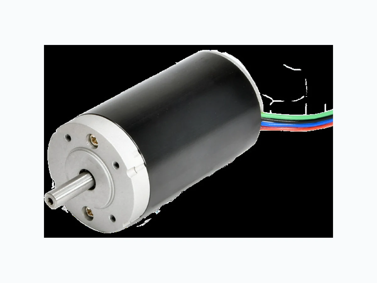
DCM-1031 ETC2
Document overview
- Manufacturer or author: Provided By digicamel.com
- PDF pages: 3
Technical content
Multi Products Company, Inc. - 5301 21st St. Racine, WI 53406 - www.multiproducts.com Highly Controllable - Extended Lifespan Brushless DC Motor Information and SpecificationsBRUSHLESS DC MOTOR Electronically commutated BLDC motors. Featuring a single frame size, neodymium magnet technology, 6 pole stator, and a slotless rotor design. Compared to brush DC motors, Multi’s Brushless DC motors are quieter, have longer service life, greater power density, and need no maintenance, making them the best option for modernization and new design-in applications. BLDC motor have three drive options available. HALL EFFECT: The Hall Effect BLDC motor is designed to connect to an external drive system utilizing the 3 onboard Hall Effect sensors for control and positioning. The choice when developing an in-house drive and controllers for design-in applications. EZ DRIVE: The EZ Drive BLDC motor utilizes an integral motor drive system. The simple on-board drive system features easy 4-lead power, brake, and forward / reverse wiring. Simple connect and go. DIGITAL DRIVE: The digital drive BLDC motor utilizes an integral motor drive system capable of using digital input / output signals from external sensors to control the speed, torque, and position of the motor. PWM or VR controller will Compatible Gearboxes / Reducers: 302, 1600, 3000, 6000, 7000(x), 9000, GBN50, GBP41, GBP52 Series Motor Specifications DC Motor Performance Little-to-no-maintenance - 20,000+ hour lifespan* Zero electromagnetic interference for external eystems Precision controllability across speed range Extruded and cast aluminum housing Heavy-duty ball bearings Features: Motor Drawing Brushless Size Small Medium Large Frame Size 42mm 42mm 42mm Reversible Yes Yes Yes Motor Life* 20000+ Hours 20000+ Hours 20000+ Hours Voltage 24V 24V 24V No Load Speed 5300 RPM 5200 RPM 4800 RPM No Load Current 0.13 A 0.14 A 0.25 A Rated Speed 4423 RPM 4619 RPM 4172 RPM Rated Current 0.75 A 1.2 A 1.7 A Stall Current 3.9 A 9.5 A 11.5 A Peak Output Power 22.5 W 53.4W 67.8 W *Estimated life - brush life dependent on duty cycle, application, and environment. DCM - 1031Hall Effect Stock Part Number: EZ Drive Stock Part Number: Digital Drive Stock Part Number: DCM - 1036 DCM - 1035
Your Partner. In Motion. - info@multiproducts.com - Toll Free: (877) 444-1011 - Main: (262) 554-3700 BLDC connections and Driver Schematics Pinouts and Schematics EZ DRIVE HALL EFFECT Hall Effect Connector Pin Out Pin No. Wire Color Signification
1 Red U Phase
2 White V Phase
3 Black W Phase
4 Green GND
5 Orange Vcc
6 Yellow Hall U
7 Blue Hall V
8 Purple Hall W
Hall Effect Firing Sequence Hall Effect Sensors CCW Phases CW Phases HU HV HW U V W U V W 1 1 0 1 + - 0 - + 0 2 1 0 0 0 - + 0 + - 3 1 1 0 - 0 + + 0 - 4 0 1 0 - + 0 + - 0 5 0 1 1 0 + - 0 - + 6 0 0 1 + 0 - - 0 + Full Driver Connector Pin Out Pin No. Wire Color Symbol I/O Function Connection
1 Red VM Input Power Supply - POS DC12V-24V +
2 Blue Brake Input Brake Operates Open or to Ground
3 Black Ground Power Supply - NEG DC12V-24V -
4 Green For/Rev Input Open: CCW
Ground: CW Open or to Ground Warning: The positive and ground wire connection is not reversible; damage to motor will result. EZ DRIVE SCHEMATIC
Multi Products Company, Inc. - 5301 21st St. Racine, WI 53406 - www.multiproducts.com BLDC connections and Driver Schematics Pinouts and Schematics DIGITAL DRIVE DIGITAL DRIVE SCHEMATIC Digital Drive Connector Pin Out Pin No. Wire Color Symbol I/O Function Standard Condition
10 White Brake Input H: Brake engages
L: Brake releases H: ≥2.4V L: ≤0.4V
4 Gray F/R Input H: CCW
L: CW H: ≥2.4V L: ≤0.4V 9 Purple 1.2 - 3.2V PWM Input Power supply positive for external speed setter Pulse-width modulation Freq.: ≤5K Hz
3 Blue 2 PPR Ouput Make a full circle 2 pulse Open collector
8 Green VREF 4V Ouput Driver 4V output Provide for high signal
2 Yellow On/Off Input Motor rotates: 4V-5V
Motor stops: ≤0.4V Semiconductor element or a switch gear on/off
7 Orange VR Power supply positive for
1 Black GND Power supply GND
6 Red VM Input Power supply positive for drive
Note: Select one of the PWM (Pin 9) or the VR (Pin 7) for speed control, connecting both simultaneously is not allowed