
DATASHEET SEARCH SITE
Document overview
- Manufacturer or author: Provided By www.digicamel.com(FREE DATASHEET DOWNLOAD SITE)
- PDF pages: 17
Technical content
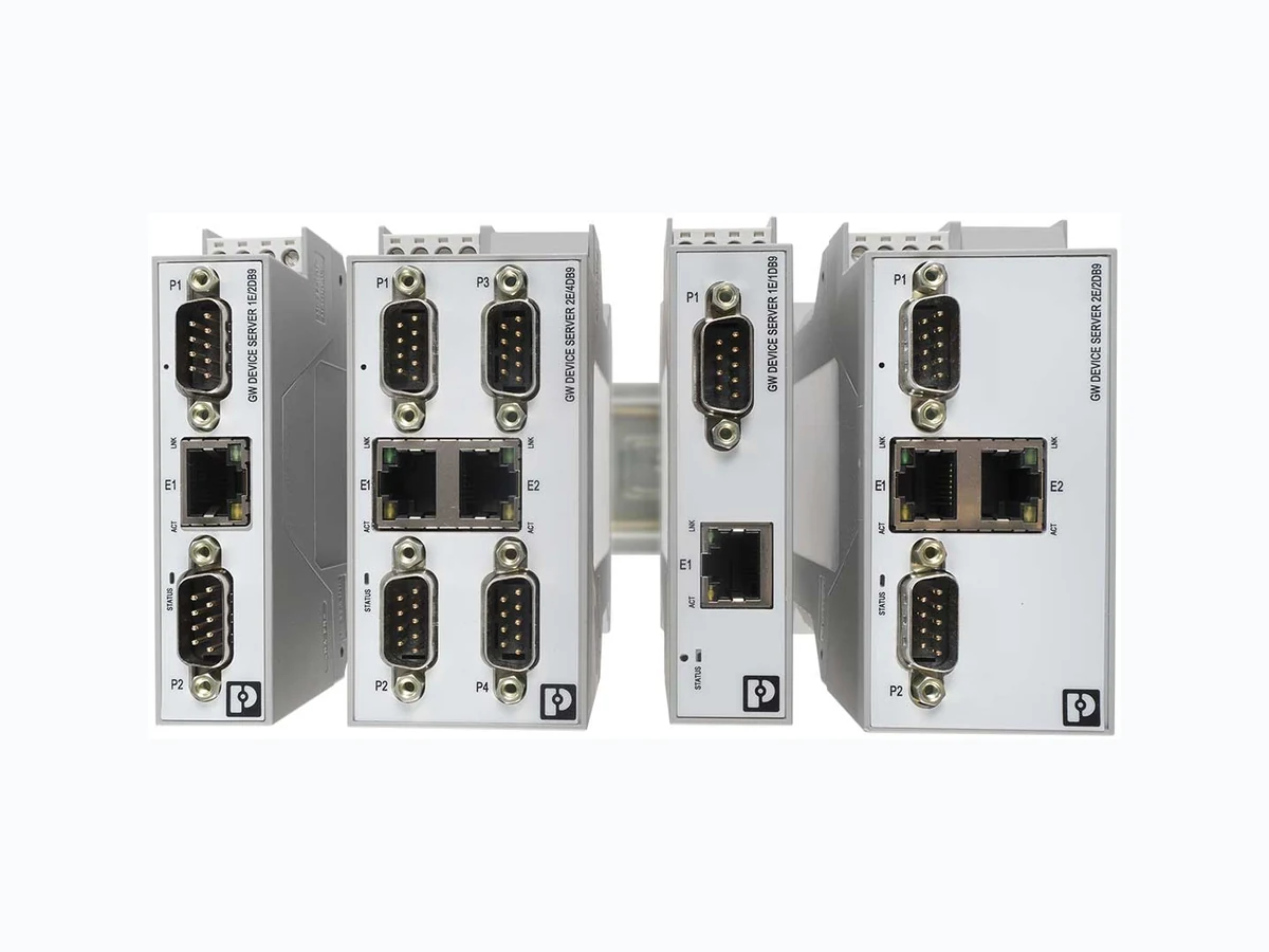
© PHOENIX CONTACT 2019-03-203750_en_C Data sheet 1D e s c r i p t i o n Ethernet gateways and device servers from Phoenix Contact provide a simple way to migrate legacy, serial devices and buses to modern Ethernet networks. Variants are available with one, two, or four D-SUB 9 serial ports and one or two RJ45 Ethernet ports. Start-up and configuration are simple using an embedded web server, and communication is kept secure with 256-bit AES encryption and optional authentication. With a wide operating temperature range (-40 to +70°C) and hazardous area approvals, the device servers and gateways are suitable for use in any industry. The most common industrial protocols are supported, with various combinations of RAW/ASCII serial data, Modbus RTU, TCP/IP, Modbus TCP, PROFINET IO, and EtherNet/IP™ technology. 2F e a t u r e s – 256-bit AES encryption for se cure transfer of sensitive data – Web-based management (WBM) configuration – Comprehensive diagnostics for fast and easy troubleshooting – Compact DIN rail-m ount form factor – COM port redirector software and Windows ® operating system COM port drivers Make sure you always use the latest documentation. It can be downloaded at phoenixcontact.net/products/. This document is valid for all products listed in the “Ordering data” on page 5 Universal gateways and device servers
3750_en_C PHOENIX CONTACT 2/17
3 Selection guide
A variety of different gateways and device servers are available in four different port combinations. The serial ports are universal RS-232/422/485. Device server The GW DEVICE SERVER… migrates legacy serial devices to modern Ethernet networks. With the aid of virtual communication ports, existing application software that only support serial communication can be redirected to the network card of a computer with a Windows ® operating system. The COM Port redirector software, as well as a Windows driver, is available for integration with a PC application free of charge. Modbus RTU to Modbus TCP The GW MODBUS TCP/RTU… co nverts serial-based Modbus RTU (or ASCII) to Modbus TCP. These modules are extremely powerful and can be configured to almost any combination of Modbus client and server, including a shared memory configuration, allowing two Modbus masters (clients) to communicate with each other. Device ID aliasing is also supported to create a “virtual” Modbus ID for Modbus slaves that do not have configurable Modbus addresses. EtherNet/IP™ to Modbus The GW EIP/MODBUS… enables bidirectional communication between EtherNet/IP and Modbus protocols. Simple integration into major manufacturer’s fully CIP-compliant controllers using implicit messaging, explicit messaging, or directly read and write to a tag or file. Supports communication with Modbus RTU/ASCII/TCP masters and slaves. ASCII to Modbus TCP The GW MODBUS TCP/ASCII… converts RAW or ASCII serial strings from barcode scanners, weigh scales, RFID tags, etc., into Modbus registers. Filtering rules may be created in the gateways in order to mask start and stop delimiters of a bar code, for example, to simplify integration into a programmable controller. ASCII to EtherNet/IP™ The GW EIP/ASCII… converts RAW or ASCII serial strings from barcode scanners, weigh scales, RFID tags, etc., into EtherNet/IP. Filtering rules may be created in the gateways in order to mask start and stop delimiters of a bar code, for example, to simplify integration into a programmable controller. ASCII to PROFINET IO The GW PN/ASCII… convert RAW or ASCII serial strings from barcode scanners, weigh scales, RFID tags, etc., into PROFINET IO. Filtering rules may be created in the gateways in order to mask start and stop delimiters of a bar code, for example, to simplify integration into a programmable controller. Description Ethernet ports (RJ45) Serial ports (D-SUB 9) GW… 1E/1DB9 one one GW… 1E/2DB9 one two GW… 2E/2DB9 two two GW… 2E/4DB9 two four
3750_en_C PHOENIX CONTACT 3/17 Protocol A Protocol B Modbus TCP master Modbus RTU/ASCII master Encapsulated in TCP/IP or UDP/IP EtherNet/IP PROFINET IO Modbus TCP master 2 2 2 6 – Modbus TCP slave 2 2 2 6 – Modbus RTU/ASCII master 22 2 6 – Modbus RTU/ASCII slave 22 2 6 – Serial RAW/ASCII 3 3 1 4 5 Ethernet RAW/ASCII 3 3 – 4 5 1G W D E V I C E S E R V E R …
2 GW MODBUS TCP/RTU…
3 GW MODBUS TCP/ASCII…
4 GW EIP/ASCII…
5G W P N / A S C I I …
6 GW EIP/MODBUS…
3750_en_C PHOENIX CONTACT 4/17 Table of contents
3750_en_C PHOENIX CONTACT 5/17 4O r d e r i n g d a t a Products Description Ty pe Order No. Pcs./Pkt. Serial device server for converting serial data (RS- 232/422/485) to Ethernet data (RJ45). Supports TCP and UDP protocols. COM port redirector software and Windows drivers are available for download. Includes one RJ45 port and one D-SUB 9 port. GW DEVICE SERVER 1E/1DB9 2702758 1 Serial device server for converting serial data (RS- 232/422/485) to Ethernet data (RJ45). Supports TCP and UDP protocols. COM port redirector software and Windows drivers are available for download. Includes one RJ45 port and two D-SUB 9 ports. GW DEVICE SERVER 1E/2DB9 2702760 1 Serial device server for converting serial data (RS- 232/422/485) to Ethernet data (RJ45). Supports TCP and UDP protocols. COM port redirector software and Windows drivers are available for download. Includes two RJ45 port and two D-SUB 9 ports. GW DEVICE SERVER 2E/2DB9 2702761 1 Serial device server for converting serial data (RS- 232/422/485) to Ethernet data (RJ45). Supports TCP and UDP protocols. COM port redirector software and Windows drivers are available for download. Includes two RJ45 ports and four D-SUB 9 ports. GW DEVICE SERVER 2E/4DB9 2702763 1 The GW MODBUS TCP/RTU… gateway converts serial based Modbus RTU (or ASCII) to Modbus TCP. Supports serial master or slave devices. Includes one RJ45 port and one D-SUB 9 port. GW MODBUS TCP/RTU 1E/1DB9 2702764 1 The GW MODBUS TCP/RTU… gateway converts serial based Modbus RTU (or ASCII) to Modbus TCP. Supports serial master or slave devices. Includes one RJ45 port and two D-SUB 9 ports. GW MODBUS TCP/RTU 1E/2DB9 2702765 1 The GW MODBUS TCP/RTU… gateway converts serial based Modbus RTU (or ASCII) to Modbus TCP. Supports serial master or slave devices. Includes two RJ45 ports and two D-SUB 9 ports. GW MODBUS TCP/RTU 2E/2DB9 2702766 1 The GW MODBUS TCP/RTU… gateway converts serial based Modbus RTU (or ASCII) to Modbus TCP. Supports serial master or slave devices. Includes two RJ45 ports and four D-SUB 9 ports. GW MODBUS TCP/RTU 2E/4DB9 2702767 1 The GW MODBUS TCP/ASCII… converts RAW or ASCII serial strings into Modbus registers. Includes one RJ45 port and one D-SUB 9 port. GW MODBUS TCP/ASCII 1E/1DB9 2702768 1 The GW MODBUS TCP/ASCII… converts RAW or ASCII serial strings into Modbus registers. Includes one RJ45 port and two D-SUB 9 ports. GW MODBUS TCP/ASCII 1E/2DB9 2702769 1 The GW MODBUS TCP/ASCII… converts RAW or ASCII serial strings into Modbus registers. Includes two RJ45 ports and two D-SUB 9 ports. GW MODBUS TCP/ASCII 2E/2DB9 2702770 1 The GW MODBUS TCP/ASCII… converts RAW or ASCII serial strings into Modbus registers. Includes two RJ45 ports and four D-SUB 9 ports. GW MODBUS TCP/ASCII 2E/4DB9 2702771 1
3750_en_C PHOENIX CONTACT 6/17 The GW EIP/ASCII… converts RAW or ASCII serial strings into EtherNet/IP™ protocol. Includes one RJ45 port and one D-SUB 9 port. GW EIP/ASCII 1E/1DB9 2702772 1 The GW EIP/ASCII… converts RAW or ASCII serial strings into EtherNet/IP™ protocol. Includes one RJ45 port and two D-SUB 9 ports. GW EIP/ASCII 1E/2DB9 2702773 1 The GW EIP/ASCII… converts RAW or ASCII serial strings into EtherNet/IP™ protocol. In cludes two RJ45 ports and two D-SUB 9 ports. GW EIP/ASCII 2E/2DB9 2702774 1 The GW EIP/ASCII… converts RAW or ASCII serial strings into EtherNet/IP™ protocol. Includes two RJ45 ports and four D-SUB 9 ports. GW EIP/ASCII 2E/4DB9 2702776 1 The GW PN/ASCII… converts RA W or ASCII serial strings into PROFINET IO protocol. Includes one RJ45 port and one D-SUB 9 port. GW PN/ASCII 1E/1DB9 1021080 1 The GW PN/ASCII… converts RA W or ASCII serial strings into PROFINET IO protocol. Includes one RJ45 port and two D-SUB 9 ports. GW PN/ASCII 1E/2DB9 1021058 1 The GW PN/ASCII… converts RA W or ASCII serial strings into PROFINET IO protocol. Includes two RJ45 ports and two D-SUB 9 ports. GW PN/ASCII 2E/2DB9 1021056 1 The GW PN/ASCII…converts RAW or ASCII serial strings into PROFINET IO protocol. Includes two RJ45 ports and four D-SUB 9 ports. GW PN/ASCII 2E/4DB9 1020882 1 The GW EIP/MODBUS… enables bidirectional communication between Modbus and EtherNet/IP. Includes one RJ45 port and one D-SUB 9 port. GW EIP/MODBUS 1E/1DB9 1062540 1 The GW EIP/MODBUS… enables bidirectional communication between Modbus and EtherNet/IP. Includes one RJ45 port and two D-SUB 9 ports. GW EIP/MODBUS 1E/2DB9 1062423 1 The GW EIP/MODBUS… enables bidirectional communication between Modbus and EtherNet/IP. Includes two RJ45 ports and two D-SUB 9 ports. GW EIP/MODBUS 2E/2DB9 1062388 1 The GW EIP/MODBUS… enables bidirectional communication between Modbus and EtherNet/IP. Includes two RJ45 ports and four D-SUB 9 ports. GW EIP/MODBUS 2E/4DB9 1062380 1 Products [...] Description Ty pe Order No. Pcs./Pkt.
3750_en_C PHOENIX CONTACT 7/17 Accessories Description Ty pe Order No. Pcs./Pkt. RS-232 cable, D-SUB 9 socket on D-SUB 9 socket, 9-wire, 1:1 PSM- KA9SUB9/BB/2METER 2799474 1 Patch cable, CAT5, assembled, 0.5 m FL CAT5 PATCH 0,5 2832263 1 Patch cable, CAT5, assembled, 5 m FL CAT5 PATCH 5,0 2832580 1 D-SUB 9 female connector, one cable entry <35°, universal type for all systems, pin assignment: 1, 2, 3, 4, 5, 6, 7, 8, 9 to screw connection terminal block SUBCON 9/F-SH 2761499 1 D-SUB 9 female connector, axial version with two cable entries, universal type for all systems, pin assignment: 1, 2, 3, 4, 5, 6, 7, 8, 9 to screw connection terminal block SUBCON-PLUS-F/AX 9 2311797 1 D-SUB 9 female connector, two cable entries < 35°, universal type for all systems, pin assignment: 1, 2, 3, 4, 5, 6, 7, 8, 9 to one screw connection terminal block SUBCON-PLUS 9/F 2744241 1 D-SUB 9 female connector, two cable entries < 35°, bus system: CAN, SUCONET K1, K2 (MOELLER), S-BUS (Saia), J-BUS (Merlin Gerin), pin assignment: 2, 3, 4, 5, 7, 9 to two screw connection terminal blocks SUBCON-PLUS F2 2799490 1 V.24 (RS-232) zero modem connector PSM-AD-D9-NULLMODEM 2708753 1 Surge protection in accordance with Class EA (CAT6A), for Gigabit Ethernet (up to 10 Gbps), token ring, FDDI/CDDI, ISDN, and DS1. Suitable for Power over Ethernet (PoE+) “Mode A” and “Mode B”. RJ45 attachment plug with separate grounding cable and ground connection snap-on foot for NS 35 DIN rails. DT-LAN-CAT.6+ 2881007 1 Ethernet switch, five TP RJ45 ports, automatic detection of data transmission speed of 10 or 100 Mbps (RJ45), autocrossing function FL SWITCH SFN 5TX 2891152 1
3750_en_C PHOENIX CONTACT 8/17
5 Technical data
Temperature range, operating -40 … +70°C Temperature range, storage/transport -40 … +80°C Permissible humidity, operation 10 … 95% non-condensing Permissible humidity, storage/transport 5 … 95% non-condensing Degree of protection IP20 Housing material PA 6.6 Color Gray Mounting NS 35 rail Height 99 mm Width 22.5 mm 45 mm Depth 115 mm Electrical data Supply voltage range 10.8 … 30 V DC Typical current consumption GW ...1E/1DB9 GW ...1E/2DB9 GW ...2E/2DB9 GW ...2E/4DB9 48 mA 76 mA 88 mA 110 mA Maximum current consumption GW ...1E/1DB9 GW ...1E/2DB9 GW ...2E/2DB9 GW ...2E/4DB9 60 mA 85 mA 100 mA 120 mA Connection data Connector type Removable Connection method Screw Stripping length 7 mm Screw thread M3 Wire-clamp screw torque 0.5 … 0.6 Nm Data interface Ethernet type 10/100Base-T(X) per IEEE 802.3 Ethernet connection type RJ45 Serial interface RS-232/422/485 Serial connection type D-SUB 9, male Termination Software configurable, 120
3750_en_C PHOENIX CONTACT 9/17
5.1 Block diagram
Electromagnetic compatibility EMC Directive 2014/30/EU Radio interference EN 55022 EN 55024 Vibration In accordance with IEC/EN 60068-2-6; 1g, 10 ... 150 Hz Shock In accordance with IEC/EN 60068-2-27; 15g, 11 ms Noise emissions EN 61000-6-4 Noise immunity EN 61000-6-2:2005 EU conformance CE-compliant Approvals UL 61010-1 UL Class I, Div. 2, Groups A, B, C, D, T4 ATEX Demko 18ATEX 2026X: II 3 G Ex ec IIC T4 Gc IECEx IECEx UL 18.0023X Ex ec IIC T4 Gc 24 V1 24 V2 0 V 51 kΩ 51 kΩ 120 Ω 120 Ω μC EEPROM SDRAM RS-232 RS-422 RS-485 Flash 3.3 V 3V3 24 V
3750_en_C PHOENIX CONTACT 10/17
5.2 Structure
6 Installation
6.1 LEDs
6.2 Data interfaces
Figure 2 shows the GW...1E/1DB9 and GW...2E/4DB9 variants. Other variants are similar.
1 Power connector
2 D-SUB 9 connector, port 1 (P1)
3 D-SUB 9 connector, port 2 (P2)
4 D-SUB 9 connector, port 3 (P3)
5 D-SUB 9 connector, port 4 (P4)
6 Ethernet port, RJ45 (E1)
7 Ethernet port, RJ45 (E2)
8 Status LED
9 Ethernet activity status LED
10 Ethernet link status LED
11 Reset button
STATUS Green The STATUS LED flashes while the device is booting (approximately 15 seconds). After booting, the LED blinks approximately every ten seconds. An internal error is indicated by three flashes every five seconds. LNK Green Link LED. On indicates Ethernet network is connected. ACT Yellow Activity LED. Flashing indicates data transfer activity.
3750_en_C PHOENIX CONTACT 11/17
6.2.1 RS-232 interface
The D-SUB 9 connector may function as an RS-232, RS-422, or RS-485 interface. The RS-232 interface is a data terminal equipment (DTE) port that behaves like a personal computer (PC). A null modem cable or adapter is required to connect to a PC. be connected (for example, a PC) by way of the PSM-KA- 9SUB 9/BB/2 METER V.24 (RS-232) cable (Order No. 2799474). The cable is an interface cable with 1:1 connected contacts.
6.2.2 RS-422, RS-485 four-wire interface
Four-wire RS-422 and RS-485 supports full-duplex communication. Phoenix Contact recommends using twisted-pair shielded cables with the shields terminated at a common point.
6.2.3 RS-485 interface
Two-wire RS-485 supports half-duplex communication. Phoenix Contact recommends using twisted-pair shielded cables with the shields terminated at a common point. Termination resistors Termination resistors must be activated on the first and last device in an application consisting of an RS-422 of a RS-485 network. The termination resistors are integrated based management interface.
6.2.4 Ethernet interface
The GW … has an Ethernet in terface on the front in RJ45 format to which only twisted-pair cables with an impedance of 100 can be connected. The data transmission rate is auto negotiation function for automatic selection of the transmission speed, as well as an automatic crossover feature for the automatic selection of line or crossover cabling. classified as a switch. When using only one port, it is a simple end-node device. The maximum number of daisy- the maximum distance between nodes, is based on the Ethernet standard and will be determined by your own environment and the conformity of your network to these standards. The V.24 (RS-232) interface of the (DTE) assignment. Pin RS-232 (DTE) Signal direction D-SUB 9 (DCE) D-SUB 9 (DTE) 1D C D < – 1 4 2R x D < – 2 3
3 TxD –> 3 2
4 DTR –> 4 1, 6
6D S R < – 6 4 7R T S – > 7 8 8C T S < – 8 7 9R I < –9 – Pin RS-422/485 4 wire Signal direction RS-422/485 4 wire
2 T(A)- <– Tx-
3 D(A)- –> Rx-
7 D(B)+ –> Rx+
8 T(B)+ <– Tx+
3 D(A)- <–> Rx/Tx-
7 D(B)+ <–> Rx/Tx+
3750_en_C PHOENIX CONTACT 12/17
7 Startup and configuration
7.1 Web-based management
The user-friendly, web-based management (WBM) gateways from anywhere in the network using a standard browser. Comprehensive configuration and diagnostic functions, including a wide range of information about the state, are clearly displayed on a graphical format. Enter the credentials to access the WBM configuration pages. The default credentials are: there are two methods available.
7.2.1 Hardware reset
The reset button allows resetting the device without the use of a PC. To force a hardware reset: 1. With the device powered off, press and hold the reset button. Apply power and hold the reset button for at least five seconds. Reinitializing the module and firmware reset may take some time. Do not disconnect from power (see Figure 2 for the location of the reset button). 2. After a successful reset, the module returns to the factory default address (192.168.254.254).
7.2.2 Software reset
- Start the WBM and navigate to the “Device Maintenance/Restore Defaults” page. 2. Click the “Check the box to confirm” check box on the page. 3. Click the “Apply Changes” button. to the factory default address (192.168.254.254). IP address: 192.168.254.254 Subnet mask: 255.255.255.0 Gateway: 0.0.0.0 User name: Admin Default password: admin
3750_en_C PHOENIX CONTACT 13/17
8 Application examples
8.1 GW DEVICE SERVER…
A common application is simple point-to-point connection of two serial devices via an Ethernet network. The data is tunneled through the network to remove any range restrictions, such as a maximum of 15 m for V.24 (RS-232). This connection also operates across sub-networks and gateways. The GW DEVICE SERVER… at each end is logically linked to the other by specifying the target and source IP addresses. Figure 4 Serial tunneling It is also possible to multiplex data from multiple serial ports on multiple GW DEVICE SERVER… servers to a single serial port on a GW DEVICE SERVER… Virtual COM port Existing application software that only communicates via serial COM interfaces can be redirected to remote COM ports. Virtual COM ports must be created on the PC that the software uses for communication. The virtual COM ports are physically redirected to the network card and a destination IP in the network. There are two options for creating virtual COM ports: the COM port redirector software, or the GW DEVICE SERVER… Windows driver. Both can be downloaded from phoenixcontact.com. Figure 5 Virtual COM port 10865 049752 100.0 kg LAN/WAN RS-232/422/485 10865 049752 100.0 kg COM1 = 192.168.254.254:8000 COM2 = 192.168.254.254:8001 LAN/WAN RS-232/422/485 IP = 192.168.254.254 Serial Port 1 = TCP port 8000 Serial Port 2 = TCP port 8001
3750_en_C PHOENIX CONTACT 14/17
8.2 GW MODBUS TCP/RTU…
Modbus RTU to Modbus TCP conversion The lifetime of legacy serial Modbus RTU/ASCII devices can easily be extended using the GW MODBUS TCP/RTU… gateways to convert to Modbus TCP. A serial Modbus slave can be connected to a Modbus TCP master, or vice versa. Figure 6 Serial Modbus RTU/ASCI I slave to Modbus TCP master Modbus master-to-master communication The “Shared Memory” feature provides a simple and robust method for Modbus master-to-master communication. In this case, the GW MODBUS TCP/RTU… emulates a Modbus slave, and each Modbus master can read or write to the “shared” memory in order to exchange data. Any serial or Ethernet-based Modbus master can access the shared memory. Figure 7 Modbus Master-to-Master co mmunication using shared memory Modbus TCP master LAN/WAN RS-232/422/485 Modbus RTU slave Modbus ASCII slaveRS-232/422/485 LAN/WAN RS-232/422/485 Shared memory Modbus Slave ID = 5 Holding Registers Start address = 400001 Coil Status Register Start address = 000001 Modbus TCP master Modbus RTU master
3750_en_C PHOENIX CONTACT 15/17 Modbus device ID offset When multiple serial Modbus slaves with fixed Device IDs are connected to multiple serial ports on the GW MODBUS TCP/RTU… it is possible to address them se parately using the Device ID offset functionality. Figure 8 Serial Modbus slaves with the same Device ID on a multiport GW MODBUS TCP/RTU…
8.3 GW EIP/MODBUS…
Flexible, bidirectional communication between EtherNet/IP controller and Modbus ASCII/RTU/TCP masters and slaves. Figure 9 EtherNet/IP to Modbus ASCII/RTU/TCP LAN/WAN RS-232/422/485 Device ID offset Port 1 Device ID Offset = 0 Port 2 Device ID Offset = +1 Port 3 Device ID Offset = +2 Port 4 Device ID Offset = +3 Modbus TCP master Modbus RTU slave Device ID = 1 Modbus RTU slave Device ID = 1RS-232/422/485 LAN/WAN RS-232/422/485 EtherNet/IP master Modbus RTU master Modbus RTU master RS-232/422/485 Modbus TCP master
3750_en_C PHOENIX CONTACT 16/17
8.4 GW MODBUS TCP/ASCII…
The ASCII to Modbus TCP gateways enable the integration of ASCII serial or TCP/IP barcode scanners, RFID readers, weigh scales, vision systems and encoders, etc., directly into a Modbus TCP control system. The ASCII strings are mapped into Modbus registers. Figure 10 Barcode scanner to Modbus connections
8.5 GW EIP/ASCII…
The ASCII to EtherNet/IP gateways enable the integration of ASCII serial or TCP/IP barcode scanners, RFID readers, weigh scales, vision systems and encoders, etc., directly into an EtherNet/IP control system. The ASCII strings are mapped into EtherNet/IP messages. Figure 11 Barcode scanner to EtherNet/IP connections 10865 049752 10865 049752 Modbus TCP master or slave LAN/WAN RS-232/422/485 Serial ASCII/RAW device Serial ASCII/RAW device RS-232/422/485 10865 049752 10865 049752 EtherNet/IP master LAN/WAN RS-232/422/485 Serial ASCII/RAW device Serial ASCII/RAW device RS-232/422/485
3750_en_C 17/17PHOENIX CONTACT GmbH & Co. KG • Flachsmarktstraße 8 • 32825 Blomberg • Germany phoenixcontact.com
8.6 GW PN/ASCII…
The ASCII to EtherNet/IP gateways enable the integration of ASCII serial or TCP/IP barcode scanners, RFID readers, weigh scales, vision systems and encoders, etc., directly into an PROFINET IO control system. The ASCII strings are mapped into PROFINET IO messages. Figure 12 Barcode scanner to PROFINET IO connections 10865 049752 10865 049752 PROFINET IO master LAN/WAN RS-232/422/485 Serial ASCII/RAW device Serial ASCII/RAW device RS-232/422/485