
DATASHEET SEARCH SITE
Document overview
- Manufacturer or author: Provided By www.digicamel.com(FREE DATASHEET DOWNLOAD SITE)
- PDF pages: 6
Technical content
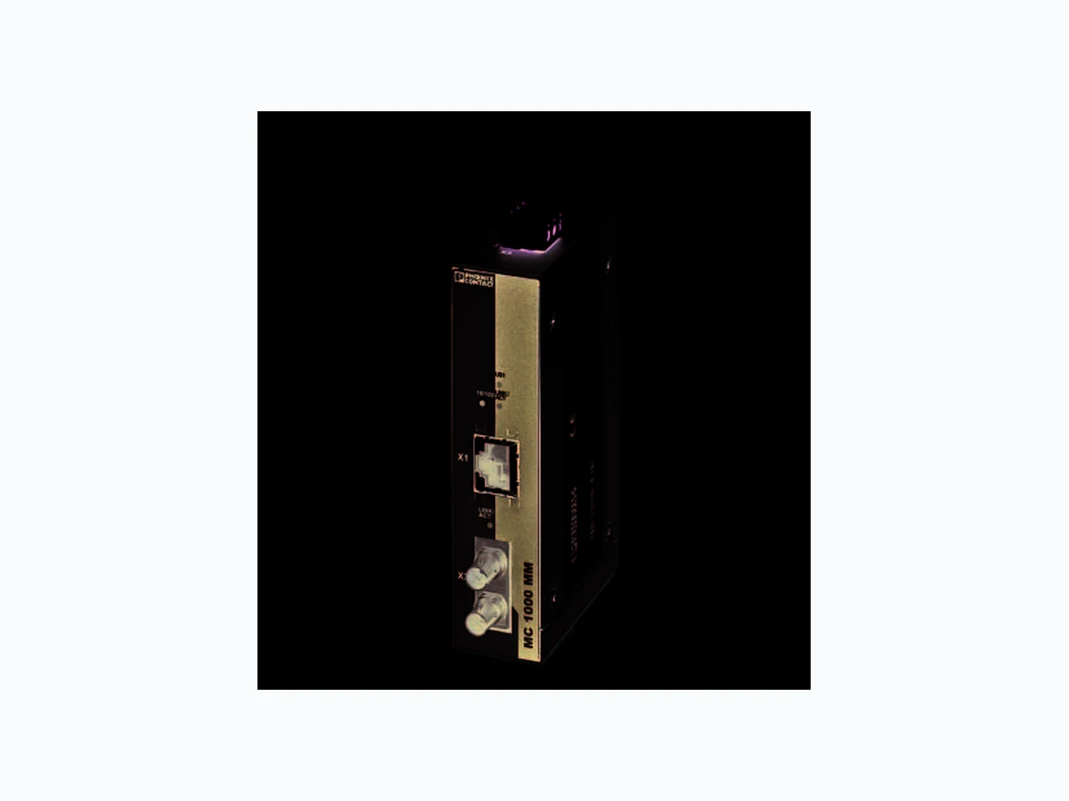
© PHOENIX CONTACT 2014-10-133384_en_A FL MC 1000 SC(ST) Data sheet 1D e s c r i p t i o n Basic media converter capability with low installed cost al- lows a high level of immunity to interference and long trans- mission range in industrial applications by converting the 10/100Base-Tx Ethernet interface to fiber optics (100 Mbps according to FX standard). The FL MC 1000… is ideal for general industrial applications. The RJ45 port offers an auto crossing function, which means it is not necessary to make a distinction between 1:1 and crossover cables. 2F e a t u r e s – 10/100Base-Tx – 0 to 60°C ambient temp erature operating range – Auto crossing simplifies cabling – Link fault pass through diagnostics – Layer 1 security for the RJ45 port – Individual LEDs at each po rt indicate communication activity and data rate – SC-duplex and ST connections – Mounts on NS 35 DIN rail Make sure you always use the latest documentation. It can be downloaded at phoenixcontact.com This data sheet is valid for all products listed on the following page: Fiber optic converter to convert 10/100Base-Tx to multi-mode fiberglass
FL MC 1000 SC(ST) 3384_en_A PHOENIX CONTACT 2 3O r d e r i n g d a t a
4 Technical data
Description Type Order No. Pcs. / Pkt. Fiber optic converter, LC connection (1310 nm), for converting 10/100Base-Tx to multi-mode fiberglass FL MC 1000 SC 2891320 1 Fiber optic converter, LC connection (1310 nm), for converting 10/100Base-Tx to multi-mode fiberglass FL MC 1000 ST 2891321 1 Accessories Description Type Order No. Pcs. / Pkt. Universal end clamp E/NS 35 N 0800886 50 Patch cable, CAT 5, pre-assembled, 0.3 m long FL CAT5 PATCH 0,3 2832250 10 Patch cable, CAT 5, pre-assembled, 0.5 m long FL CAT5 PATCH 0,5 2832263 10 Patch cable, CAT 5, pre-assembled, 1.0 m long FL CAT5 PATCH 1,0 2832276 10 Patch cable, CAT 5, pre-assembled, 1.5 m long FL CAT5 PATCH 1,5 2832221 10 Patch cable, CAT 5, pre-assembled, 2.0 m long FL CAT5 PATCH 2,0 2832289 10 Patch cable, CAT 5, pre-assembled, 3.0 m long FL CAT5 PATCH 3,0 2832292 10 Patch cable, CAT 5, pre-assembled, 5.0 m long FL CAT5 PATCH 5,0 2832580 10 Patch cable, CAT 5, pre-assembled, 7.5 m long FL CAT5 PATCH 7,5 2832616 10 Patch cable, CAT 5, pre-assembled, 10.0 m long FL CAT5 PATCH 10 2832629 10 General data Function Converter, Ethernet 10/100Base-Tx to fiber optic; conforms to standard IEEE 802.3 Housing dimensions (width x height x depth) 28 x 110 x 70 mm Weight, without connectors 315 g Operating temperature 0°C … 60°C Storage temperature 0°C … 70°C Degree of protection IP20, DIN 40050, IEC 60529 Protection class Class 3 VDE 0106; IEC 60536 Humidity (operation and storage) 5% to 95%, no condensation Air pressure (operation) 66 kPa … 108 kPa, 4850 m above sea level Air pressure (storage) 66 kPa … 108 kPa, 4850 m above sea level Mounting NS 35 (EN 60715) Preferred mounting position Perpendicular to a standard mounting rail Connection to protective earth ground Snapped onto a grounded mounting rail Latency 4 µs Supply voltage (US) Connection type Removable, screw-clamp connector Wire size (solid/stranded/AWG) 0.2 … 2.5 mm² / 0.2 … 2.5 mm² / 24 … 12 AWG Recommended PE wire size 2.5 mm 2 Nominal power supply 24 V DC, 48 V DC Permissible ripple 3.6 V pp within the permissible voltage range Permissible voltage range 12 V DC … 57 V DC Current consumption, typical 73 mA @ 24 V DC Inrush current at 48 V DC 8 A (1.8 ms) Test voltage 500 V AC for one minute Protection against polarity reversal Present
FL MC 1000 SC(ST) 3384_en_A PHOENIX CONTACT 3 Interfaces Properties of RJ45 port Total number of RJ45 Ethernet interfaces 1 Connection format RJ45 female Connection medium Twisted-pair cable with a conductor cross section of 0.14 mm2 to 0.22 mm2 Cable impedance 100 Transmission speed 10/100 Mbps Maximum network segment length 100 m MDI/MDIx switchover Automatic (auto MDI/MDIX) Properties of fiber optic port Total number of FO ports 1 Connection format SC, ST Wavelength 1310 nm Transmission speed 100 Mbps Transmission length 8 km with F-G 62.5/125 0.7 dB/km F1000 3.3 km with F-G 62.5/125 2.6 dB/km F600 9.6 km with F-G 50/125 0.7 dB/km F1200 5.3 km with F-G 62.5/125 1.6 dB/km F800 2 km with HCS GI fiber with F-GK 200/230 Mechanical tests Vibration resistance according to IEC 60068-2 10 … 150 Hz, 5g Shock test according to IEC 60068-2-24, operating 30g, 11 ms Free fall according to IEC 60068-2-32 100 cm Conformance IEC 61000-6.2 Approvals General c ROHS WEEE 2002/96/EC
FL MC 1000 SC(ST) 3384_en_A PHOENIX CONTACT 4 5D i m e n s i o n s Figure 1 Housing dimensions 6O v e r v i e w Figure 2 Connectors and LEDs
1 RJ45 port
2 Fiber optic port
3 LEDs
4 Power connector
5 DIP switch
6.1 Diagnostic and status indicators
US On Supply voltage (U S) in the tolerance range Off Supply voltage (U S) too low LNK/ACT On Indicates an electrical link Flashing Data transmission is in process (RJ45 port only) On Port is operating at 100 Mbps Off Port is operating at 10 Mbps LNK/ACT LED: ON: indicates an electrical link Flashing: indicates network traffic (at high data rates the blinking is in a constant rate)
FL MC 1000 SC(ST) 3384_en_A PHOENIX CONTACT 5
7 Installation
Install the module on a clean NS 35 rail. To avoid contact resistance use only clean, corrosion-free rails that meet the EN 60715 standard. End clamps can be mounted on both sides of the module to stop the modules from slipping on the rail.
7.1 Assembly
- Place the module onto the rail from above. The upper holding keyway must be hooked onto the top edge of the rail. 2. Push the module from the front towards the mounting surface. 3. Once the module has been snapped on properly, check that it is fixed securely on the rail.
7.2 Removal
- Insert a suitable tool (e.g., screwdriver) into the arresting latch and pull it down. 2. Pull the module slightly away from the mounting surface. 3. Lift the module from the rail.
7.3 Power connection
The device is designed for SELV and PELV operation at +24 V DC according to IEC 61140/EN 61140. Only SELV and PELV according to the defined standards may be used for supply purposes. Snapping the device onto a grounded rail connects it to the rail ground potential. Figure 3 Power connection Use power conductors between 0.2 - 2.5 mm² (24 - 12 AWG). Torque connection screws to 0.5 - 0.6 Nm (5 - 7 lb-in.).
7.4 Ethernet interface
The FL MC 1000… has one Ethern et port on the front in RJ45 format to which a twisted-pair cable with an imped- ance of 100 can be connected. The data transmission speed is 10/100 Mbps. This port has an auto crossing func- tion: it is not necessary to make a distinction between 1:1 or crossover Ethernet cables.
- Connect the twisted-pair cable to the RJ45 connector.
- Ensure the connection is secure by gently pulling it.
7.5 Fiber optic interface
- Connect the fiber optic cable to the SC-duplex or ST plug-in connector for the transmit and receive channel. Make sure the keying is in the correct position.
- Ensure the connection is secure by gently pulling it. CAUTION: Only qualified personnel may start up and operate this device. Qualified personnel are persons authorized to start up, ground and mark devices, systems and equipment according to the standards of safety technology. NOTE: The FL MC 1000 SC(ST) module is designed for SELV and PELV operation according to IEC 61140/EN 61140. NOTE: Connect the mounting rail to protective earth ground using a grounding terminal block. The modules are grounded when they are snapped onto the rail. Connect protective earth ground with low impedance. WARNING: During operation, do not look directly into transmitter diodes or use visual aids to look into the glass fibers. The infrared light is not visible. NOTE: Do not remove dust protection caps until just before the plug-in connectors are connected. They prevent contamination of the transmit and receive elements. NOTE: Observe the cable manufacturer’s technical data when handling the various fiber optic cables. In order for the communication path to be immune to interference, the permissible values for bending radius, tensile force and pressure force must not be exceeded.
FL MC 1000 SC(ST) 3384_en_A 6PHOENIX CONTACT GmbH & Co. KG • 32823 Blomberg • Germany www.phoenixcontact.com
8 Configuration
A seven-position DIP switch on the bottom surface of the FL MC 1000… allows configurat ion of operating character- istics. Figure 4 DIP switch
8.1 Link fault pass through (DIP 1)
Link fault pass through is a function that allows diagnostics from one port to pass through to the other port. The link status of the RJ45 port is always forwarded to the fiber optic port. However, link fault pass through from the fiber optic port to the RJ45 port is selectable (via DIP 1). When link fault pass through is disabled, devices may not be able to detect that the fiber optic network connection is interrupted. The connected device either doesn’t know it is not communicating (diagnostics cannot be generated) or it continually attempts to re-establish communication, increasing the network load and application response time. When enabled, a link loss at the fiber optic port is forwarded to the RJ45 port so both ports of the converter are disabled. DIP 1 can be used to enable link fault pass through (LFPT), which allows faults to propagate globally through the system, or stay local to each link segment.
8.2 Data transfer and configuration (DIP 2, 3 and 4)
8.3 Security frames
The RJ45 port accepts security frames. FL PLUG GUARD… security frames lock the RJ45 cable in place, re- ducing the chance of an unauthorized change or network access. Link fault pass through should only be used when two media converters are connected in series. DIP Position Function
1 On LFPT enabled (global) : in the event of a
fault, the entire connection is disabled. Off LFPT disabled (local ): in the event of a fault, only the interrupted part is disabled. This is useful during startup and in the event of an error. DIP Position Function
2 Off Auto-negotiation mode
On Forced mode (RJ45 port set by DIP switches 3 and 4)
3 Off Transfer rate set to 100 Mbps
On Transfer rate set to 10 Mbps
4 Off Full duplex
DIP switch positions 5, 6 and 7 are reserved for future use.