
DATASHEET SEARCH SITE
Document overview
- Manufacturer or author: Provided By www.digicamel.com(FREE DATASHEET DOWNLOAD SITE)
- PDF pages: 5
Technical content
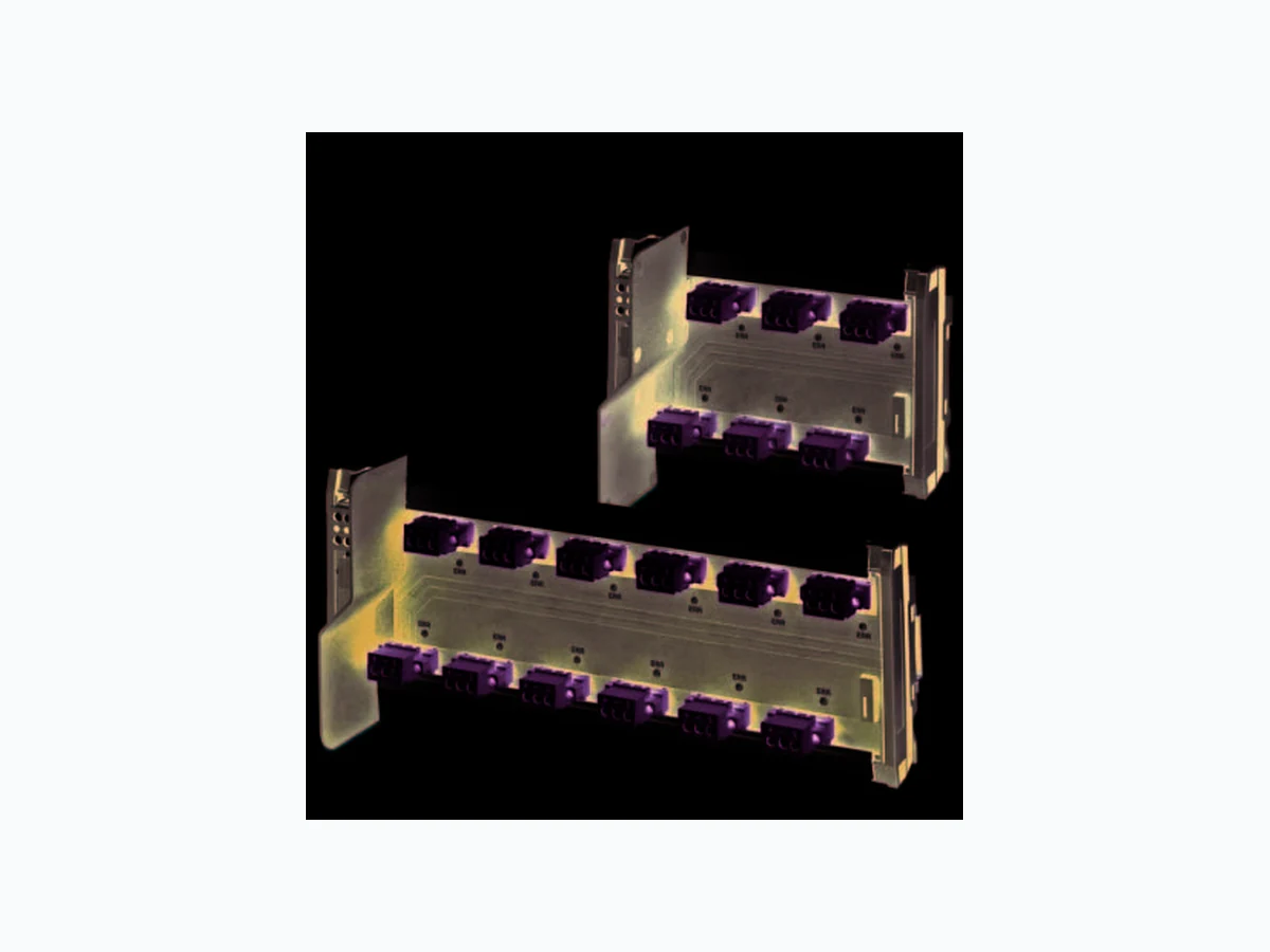
3177_en_A FB-6SP and FB-12SP Data sheet © PHOENIX CONTACT 2015-01-20 1D e s c r i p t i o n The FB-6SP and FB-12SP block couplers provide an interface between the fieldbus trunk cable and field devices on Foundation Fieldbus™ and PROFIBUS PA bus systems. Limited width on the rail reduces the required footprint and weight of the field enclosure. The FB…SP couplers connect to the trunk utilizing a T-connector terminal block with preinstalled terminator, ensuring termination is always available and error free. The block couplers feature short-circuit protection to the trunk. The single-sided plug configuration makes wiring in a field enclosure easy. Diagnostic LEDs include DC OK and spur fault on the segment. 2F e a t u r e s – Small footprint for effici ent enclosure space usage. – Provide Ex nA [nL], Ex nA [ic] or FISCO ic spur connections Make sure you always use the latest documentation. It can be downloaded at phoenixcontact.com. This data sheet is valid for all products listed on the following page: Block device couplers
3177_en_A PHOENIX CONTACT 2 3O r d e r i n g d a t a
4 Technical data
Description Type Order No. Pcs./Pkt. Device coupler, 6-spur, includes T-bus connector FB-6SP 2316307 1 Device coupler, 12-spur, includes T-bus connector FB-12SP 2316310 1 Accessories Description Type Order No. Pcs./Pkt. Field diagnostics module, legacy installations FB-DIAG/FF/LI 2316284 1 Connector, reverse, for field diagnostics module MVSTBW 2,5/ 3-STF-5,082CPBD:NZ 1707058 1 Power supply plug, 500 mA, 28 V DC FB-PS-PLUG-24DC/28DC/0.5/EX 2316132 1 Power supply base FB-PS-BASE/EX 2316145 1 Surge protective plug, for floating signal circuit PT 2X2-FF-ST 2800755 10 Base element, for four signal lines with floating ground PT 4+F-BE 2839415 10 Enclosure, 15 ports, aluminum FB-15-AL 2316187 1 Enclosure, 15 ports, stainless steel FB-15-SS 2316190 1 Enclosure, 8 ports, aluminum FB-8-AL 2316200 1 Enclosure, 9 ports, stainless steel FB-9-SS 2316213 1 General data Number of spurs FB-6SP FB-12SP Number of spurs per segment 24 Ambient temperature (operating) -50°C … 70°C Temperature (storage) -50°C … 85°C Relative humidity, non-condensing <95% Degree of protection IP20 Flammability rating, UL94 V0 Mounting NS35 (EN 60715) Weight FB-6SP FB-12SP 240 g 395 g Connections Type Removable spur and trunk connectors, screw clamp Conductor cross-section 0.5 … 2.5 mm² (24 … 12 AWG)
3177_en_A PHOENIX CONTACT 3 Electrical data Current draw, maximum per spur 35 mA Short circuit current, per spur 56 mA Supply voltage, minimum FB-6SP FB-12SP
10.5 V DC
10.6 V DC
Maximum supply voltage 32.0 V DC Rated voltage per spur ≤32.0 V Voltage drop Trunk in to trunk out Trunk in to spur out ≤0.1 V ≤1.25 V Termination, external removable plug 100 Trunk voltage protection Active if voltage exceeds 34.5 V Current consumption at no load FB-6SP with terminator FB-6SP without terminator FB-12SP with terminator FB-12SP without terminator 8.8 mA 4.8 mA 10.5 mA 6.5 mA Maximum power dissipation at maximum load and voltage FB-6SP with terminator FB-12SP with terminator 0.29 W 0.34 W Hazardous location ratings Temperature, Ta -50°C … 90°C Voltage, Uo Uin Current, Io 56 mA Capacitance, Ci 0 µA Inductance, Li 4 µF Capacitance, Co 80 nF Inductance, Lo 0.26 mH Conformance Shock resistance 30g, 11 ms Vibration resistance 5g, 10-150 Hz Foundation Fieldbus FF-846 IEC 60529, 61158-2 NE NE21 EN EN 61326, EN 60068-2-27, EN 60068-2-6 Approvals ATEX Sira 13ATEX4247X; II 3(3)G Ex nA [ic] IIC T4 Gc, Entity/FISCO ic spurs Ex nA [nL] IIC T4 Gc; II 3G Ex ic IIC T4 Gc, FISCO ic IECEx IECEx SIR 13.0089X; Ex nA [ic] IIC T4 Gc, Entity/FISCO ic spurs; Ex nA [nL] IIC T4 Gc; Ex ic IIC T4 Gc, FISCO ic CSA Class I, Div. 2, Groups A, B, C, D Ex nA [nL] IIC T4; Class I, Zone 2, AEx nA [nC] IIC T4
3177_en_A PHOENIX CONTACT 4
5 Dimensions
Figure 3 FB-6SP circuit diagram Figure 4 FB-12SP circuit diagram 148.283.2 112.5 92.3 ERR 4 FB-6SP ERR 6ERR 2 PWR ERR 3 ERR 5ERR 1 ERR 4 FB-12SP ERR 6ERR 2 ERR 10 ERR 12ERR 8 PWR ERR 3 ERR 5ERR 1 ERR 9 ERR 11ERR 7 254.183.2 112.5 92.3 I S11+ S11– S11S I S10+ S10– S10S I S12+ S12– S12S I S2+ S2– S2S I S3+ S3– S3S I S1+ S1– S1S V Ti+ Ti– TiS To+ To– ToS I S12+ S12– S12S V I S11+ S11– S11S I S10+ S10– S10S I S9+ S9– S9S I S8+ S8– S8S I S7+ S7– S7S I S2+ S2– S2S I S3+ S3– S3S I S4+ S4– S4S I S5+ S5– S5S I S6+ S6– S6S I S1+ S1– S1STi+ Ti– TiS To+ To– ToS
3177_en_A 5PHOENIX CONTACT GmbH & Co. KG • 32823 Blomberg • Germany www.phoenixcontact.com
7 Installation
7.1 Mounting
The block coupler installs on NS35 (EN 50022) mounting rail. 1. Secure the rail to an appropriate surface. 2. Place the block coupler onto the DIN rail from above. The upper holding keyway must be hooked onto the edge of the DIN rail. 3. Push the block coupler from the front toward the mounting surface, making sure both sides of the coupler snap onto the rail.
7.2 Connections
Foundation Fieldbus and PROFIBUS PA network configurations are bus-type networks. Each device coupler includes removable connectors. Table 1 shows the trunk and spur connections. where n indicates the spur number. Couplers may have multiple spur connectors. 8O p e r a t i o n
8.1 LEDs
Each spur has a dedicated LED. Only one device can be connected to each spur. Connection Label Function Trunk TiS Trunk in shield Ti- Trunk in - Ti+ Trunk in + ToS Trunk out shield To- Trunk out - To+ Trunk out + Spur S nSS p u r n shield Sn-S p u r n - Sn+S p u r n + Label Indicator Meaning PWR Solid green Power is present Off No power is applied ERR Solid red Short circuit in spur n Off Normal operation