
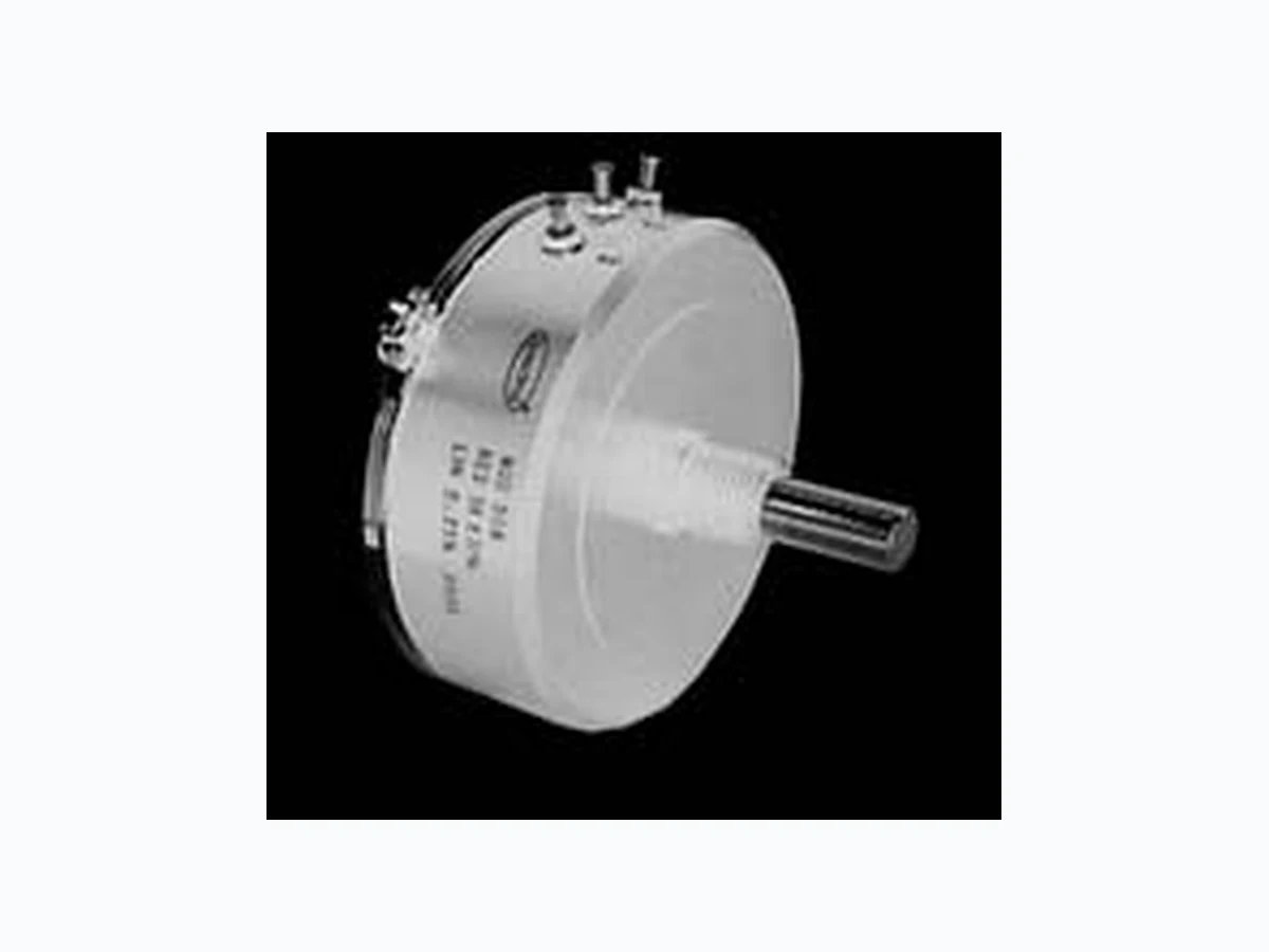
308 VISHAY
Document overview
- Manufacturer or author: Provided By www.digicamel.com(FREE DATASHEET DOWNLOAD SITE)
- PDF pages: 4
Technical content
www.vishay.com Vishay Spectrol Revision: 27-Mar-15 1 Document Number: 57058 For technical questions, contact: sferprecisionpot@vishay.com THIS DOCUMENT IS SUBJECT TO CHANGE WITHOUT NOTICE. THE PRODUCTS DESCRIBED HEREIN AND THIS DOCUMENT ARE SUBJECT TO SPECIFIC DISCLAIMERS, SET FORTH AT www.vishay.com/doc?91000 2" (50.8 mm) Single Turn Conductive Plastic Precision Potentiometer
FEATURES
- Bushing mount and servo mount types available
- Virtually infinite resolution
- Up to 6 sections available
- Rotational life exceeds 20 million shaft revolutions
- Co-molded track and multi-finger wiper provide low noise signal
- Large ohmic value range: 500 to 100 k
- Material categorization: fo r definitions of compliance please see www.vishay.com/doc?99912 QUICK REFERENCE DATA Sensor type ROTATIONAL , conductive plastic Output type Output by turrets Market appliance Professional Dimensions 2" (50.8 mm) ELECTRICAL SPECIFICATIONS PARAMETER Total resistance standard range 500 to 100 k Tolerance STANDARD ± 10 % SPECIAL ± 5 % Linearity (independent) STANDARD ± 0.25 % SPECIAL ± 0.05 % Electrical angle 350° ± 2° Power rating Section 1 Additional sections
2.0 W at 70 °C ambient derated to zero at 125 °C (400 V
DC maximum) 75 % of the rating of section 1 Output smoothness 0.1 % maximum Insulation resistance 1000 M minimum, 500 VDC Dielectric strength 1000 V RMS, 60 Hz Taps (extra) Extra taps available as special Phasing Points at which output ratio is 0.5 aligned ± 1° (ref. to section 1) Temperature coefficient of resistance ± 600 ppm/°C maximum
ORDERING INFORMATION
MODEL STYLE GANGS OHMIC VALUE GANGS No 1 OHMIC VALUE GANGS No 2 SPECIAL REQUEST
308 B : bushing
S: servo 470 = 47 222 = 2.200 103 = 10 k For ohmic value range see electrical specification 470 = 47 222 = 2.200 103 = 10 k For ohmic value range see electrical specification xxxx PART NUMBER DESCRIPTION (for information only) 308- 1 2 103 203 xxxx MODEL STYLE GANGS OHMIC VALUE GANGS No 1 OHMIC VALUE GANGS No 2 SPECIAL B: 1 S: 2
www.vishay.com Vishay Spectrol Revision: 27-Mar-15 2 Document Number: 57058 For technical questions, contact: sferprecisionpot@vishay.com THIS DOCUMENT IS SUBJECT TO CHANGE WITHOUT NOTICE. THE PRODUCTS DESCRIBED HEREIN AND THIS DOCUMENT ARE SUBJECT TO SPECIFIC DISCLAIMERS, SET FORTH AT www.vishay.com/doc?91000 DIMENSIONS in inches (millimeters) MECHANICAL SPECIFICATIONS PARAMETER Rotation 360° (continuous) Bearing type Servo mount: Bushing mount: Ball bearing Sleeve bearing Ganging 6 sections maximum. Terminal alignment, a dded sections, within ± 10° of section 1 terminals Torque (maximums) Mounting Servo, 1 section Bushing, 1 section Each additional section STARTING 1.0 oz. - in (72.00 g - cm) 1.7 oz. - in (122.40 g - cm) 0.6 oz. - in (43.20 g - cm) RUNNING 0.5 oz. - in (36.00 g - cm) 1.0 oz. - in (72.00 g - cm) 0.4 oz. - in (28.80 g - cm) Runouts (maximums) Shaft (TIR/in) Pilot dia. (TIR) Lateral (TIR) Shaft end Play Shaft Radial play SERVO 0.002" (0.05 cm) 0.002" (0.05 cm) 0.003" (0.08 cm) 0.005" (0.13 cm) 0.002" (0.05 cm) BUSHING 0.002" (0.05 cm) 0.002" (0.05 cm) 0.005" (0.13 cm) 0.005" (0.13 cm) 0.003" (0.08 cm) Moment of inertia 2.0 g - cm 2 per section maximum Weight Single section Each additional section 4.0 oz. (127.57 g) 1.2 oz. (34.02 g) 0.831 (21.10) ± 0.010 0.625 (15.88) ± 0.031 0.073 MIN. (1.85) Ø 2.000 (50.80) Ø 1.8750 (47.62) + 0.0000 - 0.0005 Ø 0.2497 (6.34) + 0.0000 - 0.0003 0.062 (1.57)MTG. FACE Ø 2.000 (50.80) ± 0.015 Ø 1.812 MAX. (46.02) 0.093 (2.36) 0.340 MIN. (8.64) 15° TYP. 45° ± 5° 3 1.200 R MAX. (30.48) 1.140 R MAX. (28.96) SERVO MOUNT: 308S/308-2 BUSHING MOUNT: 308B/308-1 Ø 2.000 (50.80) ± 0.015 Ø 1.375 (34.92) ± 0.015 Ø 0.4062 (10.32) + 0.0000 - 0.0010 3/8 - 32 UNEF - 2A MTG. FACE 0.010 (0.25) 0.239 MIN. (6.07) 0.705 (17.91) ± 0.015 0.875 (22.22) ± 0.031 0.375 (9.52) ± 0.010 0.062 (1.57) Ø 0.2497 (6.34) + 0.0000 - 0.0003 1 ADD 0.500 ± 0.002 (12.70) FOR EACH ADDITIONAL SECTION TOLERANCES: UNLESS OTHERWISE NOTED. DECIMALS ± 0.005 ANGLES ± 2° CW SCHEMATIC
www.vishay.com Vishay Spectrol Revision: 27-Mar-15 3 Document Number: 57058 For technical questions, contact: sferprecisionpot@vishay.com THIS DOCUMENT IS SUBJECT TO CHANGE WITHOUT NOTICE. THE PRODUCTS DESCRIBED HEREIN AND THIS DOCUMENT ARE SUBJECT TO SPECIFIC DISCLAIMERS, SET FORTH AT www.vishay.com/doc?91000 POWER RATING CHART (Ratings for cup No. 1. Additi onal cups 75 % of values shown) Note
- Nothing stated herein shall be construed as a guarantee of quality or durability. Note (1) Maximum voltage allowable MATERIAL SPECIFICATIONS Housing and lids Aluminum, anodized Shaft and clamp rings Stainless steel, non-magnetic non-passivated Terminals Brass, gold plated for solderability Bushing mount hardware Lockwasher internal tooth: Panel nut: Steel, nickel plated Brass, nickel plated MARKING Unit identification Units shall be marked with Spectrol name, model no, and data code, and on each section, resistance, resistance tolerance, linearity and terminal identification. Example of a marking for a standard part: 308-21503AMBIENT TEMPERATURE IN °C RATED POWER IN W 20 40 60 80 100 120 140 160 ENVIRONMENTAL SPECIFICATIONS Vibration 15 g thru 2000 Hz Shock 50 g Salt spray 96 h Rotational life Servo: 20 million shaft revolutions Bushing: 5 million shaft revolutions Load life 900 h Temperature range -55 °C to +125 °C RESISITANCE ELEMENT DATA RESISTANCE VALUES () MAXIMUM VOLTAGE APPLICABLE (V) 500 32 1K 45 2K 71 5K 100 10K 141 20K 224 50K 316 100K 350 (1)
www.vishay.com Vishay Revision: 01-Jan-2022 1 Document Number: 91000 Disclaimer ALL PRODUCT, PRODUCT SPECIFICATIONS AND DATA AR E SUBJECT TO CHANGE WITH OUT NOTICE TO IMPROVE RELIABILITY, FUNCTION OR DESIGN OR OTHERWISE. Vishay Intertechnology, Inc., its affiliates, agents, and employee s, and all persons acting on it s or their behalf (collectivel y, “Vishay”), disclaim any and all liability for any errors, inaccuracies or incompleteness contained in any datasheet or in any other disclosure relating to any product. Vishay makes no warranty, representation or guarantee regarding the suitability of the products for any particular purpose or the continuing production of any product. To the maximum extent permitted by applicable law, Vishay disclaims (i) any and all liability arising out of the application or use of any product , (ii) any and all liability, including without limitation specia l, consequential or incidental damages, and (iii) any and all implied warranties, incl uding warranties of fitness for particular purpose, non-infringement and merchantability. Statements regarding the suitability of pro ducts for certain types of applications are based on Vishay's knowledge of typical requirements that are often placed on Vishay products in ge neric applications. Such statements are not binding statements about the suitability of products for a particular application. It is the customer's responsibility to validate that a particular product with the properties described in the product specification is suitable for use in a particular application. Parameters provided in datasheets and / or specificat ions may vary in different applications and performance may vary over time. All operating parameters, including typical parameters, must be validated for each customer application by the customer's technical experts. Product specifications do not expand or otherwise modify Vishay's terms and conditions of purchase, including but not limited to the warranty expressed therein. Hyperlinks included in this datasheet may direct users to third-party websites. These links are provided as a convenience and for informational purposes only. Inclusion of these hyperlinks does not constitute an endorsement or an approval by Vishay of any of the products, services or opinions of the corporation, organization or individual associated with the third-party website. Vishay disclaims any and all liability and bears no responsibility for the accuracy, legality or content of the third-party web site or for that of subsequent links. Except as expressly indicated in writing, Vishay products are not designed for use in medical, life-saving, or life-sustaining applications or for any other application in which the failure of the Vishay product could result in personal injury or death. Customers using or selling Vishay products not expressly indicated for use in such applications do so at their own risk. Please contact authorized Vishay personnel to obtain written terms and conditions regarding products designed for such applications. No license, express or implied, by estoppel or otherwise, to any intellectual property rights is granted by this document or by any conduct of Vishay. Product names and markings noted herein may be trademarks of their respective owners. © 2022 VISHAY INTERTECHNOLOGY, INC. ALL RIGHTS RESERVED