
DATASHEET SEARCH SITE
Document overview
- Manufacturer or author: Provided By www.digicamel.com(FREE DATASHEET DOWNLOAD SITE)
- PDF pages: 7
Technical content
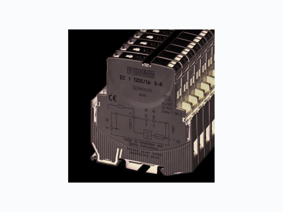
3023_en_B EC 1 12DC… Data sheet © PHOENIX CONTACT 2014-04-09 1D e s c r i p t i o n The EC 1 12DC… electronic circuit breakers selectively protect 12 V DC load circuits in hazardous and non- hazardous environments. A combination of an active electronic current limit for short circuits and an overload shutdown ensures that the EC 1 12DC… will quickly react to an over-current condition in the protected circuit. Current limitation restricts fault current to 1.5 - 1.8 times the nominal current rating (I N). As a result, the EC 1 12DC… can prevent the loss of the DC output voltage sometimes experienced when a faulted circuit triggers a switched-mode power supply into self-protected output-shutdown mode. Capacitive loads of up to 75,000 µF can be protected. The EC 1 12DC… electronic circuit breakers are available with nominal current ratings from 1 to 10 A. Local status indication is provided by a multi-color LED, and remote status indication is available via status output (+12 V = OK). Manual on/off and reset is accomplished using the integrated slide switch. Remote reset (EC 1 12DC… S-R) and remote on/off (EC 1 12DC… S-C) versions are available. The EC 1 12DC… can be snapped onto 35 mm mounting rails (EN 50022) for fast and easy installation. At just 12.5 mm wide, it requires only a small space on the rail. Screw connection technology provides secure and reliable wire connection. The integrated current distribution system is another advantage of the EC 1 12DC… circuit breakers. Wiring can be implemented easily using available busbar. 2F e a t u r e s – Selective load protection – Current limitation on overload/short circuits – Protection for capacitive circuits up to 75,000 µF – Current ratings from 1 to 10 A – Manual on/off/reset slide switch – Electronic reset option – Electronic on/off option – 12.5 mm width for minimal rail footprint – Bridging available for line (+) and return (-) – Remote status indication (+12 V = OK) –M u l t i - c o l o r s t a t u s L E D s This equipment is suitable for use in Class I, Division 2, Groups A, B, C, D or non-hazardous locations only. Make sure you always use the latest documentation. It can be downloaded at phoenixcontact.com This data sheet is valid for all products listed on the following page:
12 V DC electronic circuit breakers
EC 1 12DC… 3023_en_B PHOENIX CONTACT 2 3O r d e r i n g d a t a
4 Technical data
Description Type Order No. Pcs. / Pkt. Electronic circuit breaker, 1 A, 12 V DC, on/off control input and status output EC 1 12DC/1A S-C 3000754 1 Electronic circuit breaker, 2 A, 12 V DC, on/off control input and status output EC 1 12DC/2A S-C 3000755 1 Electronic circuit breaker, 3 A, 12 V DC, on/off control input and status output EC 1 12DC/3A S-C 3000756 1 Electronic circuit breaker, 4 A, 12 V DC, on/off control input and status output EC 1 12DC/4A S-C 3000757 1 Electronic circuit breaker, 6 A, 12 V DC, on/off control input and status output EC 1 12DC/6A S-C 3000758 1 Electronic circuit breaker, 10 A, 12 V DC, on/off control input and status output EC 1 12DC/10A S-C 3000759 1 Electronic circuit breaker, 1 A, 12 V DC, reset input and status output EC 1 12DC/1A S-R 3000760 1 Electronic circuit breaker, 2 A, 12 V DC, reset input and status output EC 1 12DC/2A S-R 3000761 1 Electronic circuit breaker, 3 A, 12 V DC, reset input and status output EC 1 12DC/3A S-R 3000762 1 Electronic circuit breaker, 4 A, 12 V DC, reset input and status output EC 1 12DC/4A S-R 3000763 1 Electronic circuit breaker, 6 A, 12 V DC, reset input and status output EC 1 12DC/6A S-R 3000765 1 Electronic circuit breaker, 10 A, 12 V DC, reset input and status output EC 1 12DC/10A S-R 3000766 1 Accessories Description Type Order No. Pcs. / Pkt. Busbar, 500 mm, can be cut to length, gray FBST 500 TMC-N GY 0901028 10 Data values at TA = 25°C, US = 12 V DC Operating data Nominal voltage US 12 V DC Voltage range 9 … 18 V DC Nominal current IN See “Current rating” on page 3 Closed-circuit current I0 When on: 15 … 20 mA typical Shutdown time, typical 3 s at I Load > 1.1 x IN 50 ms … 3 s at I Load >1.8 IN (or 1.5 x IN) Load circuit Load output Power MOSFET switch ing output (positive switching) Overload shutdown Typically 1.1 x IN (1.05 … 1.35 x I N) Short-circuit current IK Active current limitation (see “Current rating” on page 3) Temperature shutdown Internal temperature monitoring with electronic disconnect Undervoltage monitoring for load output after each switch-on procedure With hysteresis at voltag e dips <500 ms, no reset required: load “off” at UB < 3.2 V Switch-on delay tStart (typical) 10 ms Free running circuit Externa l free-wheeling diode recommended for inductive load Parallel connection of multiple load outputs Not permitted
EC 1 12DC… 3023_en_B PHOENIX CONTACT 3 Connection data Line+/Load+/0 V Thread size M4 Conductor size 1 solid or stranded conductor 2 solid or stranded conductors with same cross-section 2 stranded conductors with TWIN ferrule 0.5 … 10 mm² with or without ferrule 0.5 … 4 mm² without ferrule; 0.5 … 2.5 mm² with ferrule 0.5 … 6 mm² Stripping length 10 mm Tightening torque 1.5 … 1.8 Nm Signal connections Thread size M3 Stranded conductor size with ferrule 0.25 … 2.5 mm² Stripping length 8 mm Tightening torque 0.5 … 0.6 Nm General data Mounting DIN rail in acc. with EN 50072 (NS 35 x 7.5) Degree of protection IP20 Temperature range, operation Ordinary location Hazardous location (Class I, Div. 2) -20 … 60°C 0 … 25°C Temperature range, storage -20 … 70°C Weight 65 g Status and control Status LED Green: power applied Orange: overload or short circuit leading to electronic shutdown condition Red: electronically disconnected; low voltage (<3.25 V); load circuit/power- MOSFET off Off: under voltage or no power; manually switched off Terminals Gnd (–) NC signal contacts NO signal contacts Remote control/reset Status output Pin 3 Pin 21/22 Pin 23 Switching capacity I CN Active current limitation Expected life with 1 x IN 10000 cycles Current rating Current rating, IN ( A ) 123461 0 Voltage drop, typical, at IN (mV) 80 130 80 100 130 150 Maximum load current at 40°C at 100% duty cycle (A) 1 2 3 4 6 10 Maximum load current at 50°C at 100% duty cycle (A) 1 2 3 4 5 9 Approval/conformance Vibration 3g tested in acc. with IEC 60068-2-6, test Fc Conformance with EMC Directive 2004/108/EC Noise emission: EN 61000-6-3 Noise susceptibility: EN 61000-6-2 Insulation coordination (IEC 60934) 0 .5 kV/2 pollution degree 2, increased insulation in actuation area
EC 1 12DC… 3023_en_B PHOENIX CONTACT 5
5 Operating characteristics
5.1 Information requir ed for UL approval
Periodically inspect the EC 1 12DC… for any degradation of properties and replace if degradation is found. Figure 3 UL-approved package slip
5.2 Time/current characteristics
The trip time is typically 3 s in the range between 1.1 and 1.8 x IN Electronic current limitation typically occurs at 1.8 x IN which means that, under all overload conditions (independent of the power supply and the resistance of the load circuit), the maximum overload before disconnection will not exceed 1.8 x IN times the current rating. Trip time is between 100 ms and 3 s (depending on overload or at short circuit). Without this current limitation, a considerably higher overload current would flow in the event of an overload or short circuit. Figure 4 Time/current characteristic curve WARNING: Exposure to some chemicals may degrade the sealing properties of materials used in EC 1 12DC…. These products use the following materials: Sealing material: – Generic name: Modified diglycidyl ether of bisphenol A – Supplier: Fine Polymers Corporation – Type: Epi Fine 4616L-160PK Casing material: – Generic name: Liquid crystal polymer – Supplier: Sumitomo Chemical – Type: E4008, E4009 or E6008 WARNING: Explosion hazard Do not disconnect equipment unless power has been removed or the area is known to be non- hazardous. Substitution of any components may impair suitability for hazardous locations. This device is suitable for use in Class I, Div 2, Groups A, B, C, D; TC T5; UL File# E324415 Warnings: 1. Remove power before disconnecting device. 2. Components substitutions may impair suitability of Class I, Div 2. 3. Chemical exposure may degrade internal relay's sealing property in the EC-E1 and EC-E4 products only. Electronic Circuit Protector EC-E, EC-E1, EC-E4, EC1 UL2367 UL1604 Non-hazardous use - UL File# E317172 Refer to data sheet / installation guidelines for installation and safety instructions. PHOENIX CONTACT GmbH & Co.KG Flachsmarktstraße 8 32825 Blomberg . Germany Fax +49-(0)5235-3-4 1200 1 Current limitation is typically 1.8 x IN times rated current at IN = 0.5 A to 6 A Current limitation is typically 1.5 x IN times rated current at IN = 8 A or 10 A Disconnection (typical) 1.1 x IN current limitation typically 1.8 x IN IK 10000 1000 1 2 4 trip time in seconds ...times rated current 100 0. 1 0.01 3 50 1.8 x IN
EC 1 12DC… 3023_en_B PHOENIX CONTACT 6
6 Installation
The EC 1 12DC… features an integrated power distribution system. Figure 5 Mounting options and components NOTE: A 0 V connection is required for the EC 1 12DC…. A maximum of 10 insertion/removal cycles are allowed for busbars. When mounted side-by-side without airflow between the electronic circuit breakers, current load should be reduced to 80% of rated load when operating at a 100% duty cycle. Busbars should be interrupted and re-connected every 10 devices. Bus bar (0 V) 09010281
1 IMAX = 50 A when connected with a single input wire to the center of the bar
IMAX = 63 A when connected with two input wires, one at each end of the bar Remove protection slides from bottom side. Insert bridges and protection slides to be flush with housing sides. Insert protection slides to sides of device. 12.5 x n = width of protector block e.g., 12.5 x 5 = 62.5 mm (12.5 x n) -3 = length of bus bars ±0.5 Bus bar (Line) 09010281
EC 1 12DC… 3023_en_B 7PHOENIX CONTACT GmbH & Co. KG • 32823 Blomberg • Germany www.phoenixcontact.com When the breaker is on, 12 V DC is available at the Status Output (terminal 23) (see Figure 2 for terminal locations). Figure 6 EC 1 12DC… S-R signal inputs/outputs EC 1 12DC… S-R breakers with remote reset option may be remotely reset by the trailing edge of a +12 V DC pulse applied to the Reset Input (terminal 22). Figure 7 EC 1 12DC… S-C signal inputs/outputs EC 1 12DC… S-C breakers with remote control option may be turned on/off by cycling the +12 V DC applied to terminal 21. WARNING: Ensure that all personnel are clear before applying a reset to multiple circuit breakers. While breakers that are on will be unaffected, any breakers that were electronically tripped due to an overload condition will be turned on. LINE+ 1 SF 23 RE 22