
3000-U32-00 EMKA
Document overview
- Manufacturer or author: Provided By www.digicamel.com(free datasheet download site)
- PDF pages: 2
Technical content
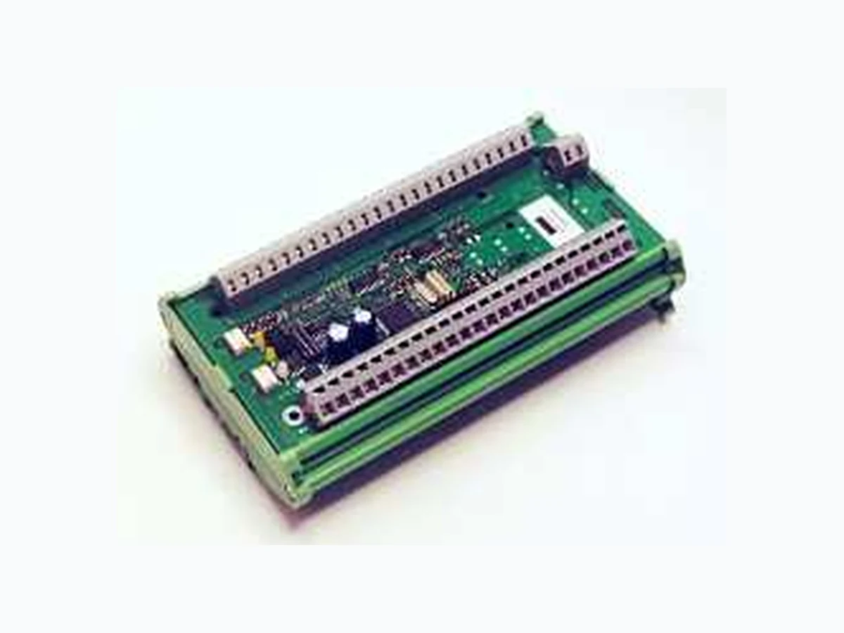
Electronic Locking & Monitoring 3 0 0 0 -U 32-0 0 © EMKA Electronic, all rights reserved Rev . 20 11-07-11 / Roh -Art. -Nr. 1 474 Page 1 of 2 Steuermodul für 8 Einpunkt-Verriegelungen – Baufo rm Kit Das Modul 3000-U32-00 ist Bestandteil des ELM Syste ms. Es bietet 8 unabhängige Ports zur Steuerung von Einpunkt- Verriegelungen. Alternativ kann an jeden Port ein p otenzialfreier Türkontakt zur Überwachung des Türzu standes (AUF/ZU) angeschlossen werden. Technische Änderungen vorbehalten. Latch module for 8 Latches – Kit style The 3000-U32-00 module is part of the ELM system. I t has 8 independent ports to control latches. Door contacts can be connected to each port to monitor the door status ( OPEN/CLOSED) in addition to the standard latch lock ed/unlocked status monitoring. Subject to technical changes. Power supply: 12 V DC, 140 mA + latch output (s) Note that for modules connected to CAN1 powe r can additionally be fed via connectors J1-1 and J1-2. Latch output: max. 12 V / 300 mA or max. 24 V / 130 mA LED CAN: flashing when active, otherwise ON LED STC: Normally OFF, flashing when module sta tus is changed Dimensions: 90 x 50 x 152 mm (W x H X D) Board: H1m11v2e2 Fig. 1: 3000-U32-00 Addressing The module address is assigned by the dip switch. The address is the sum of the address values of switches set to “OFF”. In the example on the left, address is set to “1” (only the switcher D/1 is act ive). Address “3” would mean setting dip switch “D1” and “D/2” to “OFF”. When all 6 address switches are set to “ON” , the address is assigned dynamically via software command. CAN Bus If the module is the first or the last in the modul e chain then the CAN Bus termination switch must be set to “ON”, otherwise “OFF”. This is essential for correc t operation! Note If no external power supply is connected to J3-1 / J3- 2, a cable must be pulled from J3-2 to J1-3. Then latches are operated via supply voltage of the modu le. Fig. 2: Schematic diagram
Electronic Locking & Monitoring 3 0 0 0 -U 32-0 0 © EMKA Electronic, all rights reserved Rev . 20 11-07-11 / Roh -Art. -Nr. 1 474 Page 2 of 2 Fig. 3 Wiring diagram