
3000-U140-00 AMKA
Document overview
- Manufacturer or author: Provided By www.digicamel.com(free datasheet download site)
- PDF pages: 1
Technical content
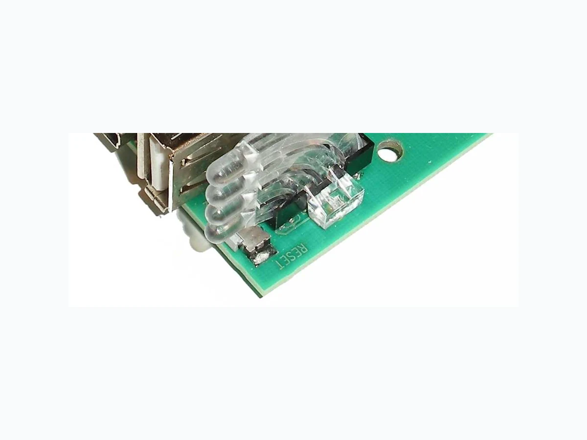
Electronic Locking & Monitoring 3 0 0 0 -U 1 4 0 -00 ( V 0 . 1 ) © EMKA Electronic, all rights reserved Rev . 20 12-10-15 / Roh -Art. -Nr. 205 0 Page 1 of 1 Kommunikationsmodul – Bauform Kit Das Kommunikationsmodul 3000-U140-02 ist Bestandtei l des ELM Systems. Es beinhaltet die zentrale Syste m-Steuereinheit einschließlich Ereignisspeicher mit Schnittstellen zur Konfiguration und Kommunikation und 2 Alarmrela is. Zusätzlich ist ein analoger Sensor aus dem ELM Programm anschließbar. Pro ELM System kann nur ein Kommunikationsmodul ein gesetzt werden. Technische Änderungen vorbehalten. Communications module – Kit style The communications module 3000-U140-02 module is pa rt of the ELM system. It contains the central contr ol unit for the system with event memory, interfaces for system con figuration and communication and 2 alarm relays. In addition an analog ELM sensor can be connected. Only one communication s module can be used in an ELM system. Subject to technical changes. Power supply: 12 V DC, 350 mA Relay data: max. 48 V AC, max. 0.5 A, max. 30 V DC, max. 1.0 A Data interfaces: RS 232 Sub-D9, USB (front) Ethernet RJ45 (rear) LED CAN: flashing when active, otherwise ON LED CYC: flashing when polling cycle is complet e LED NWR/NWT: flashing when receiving / transmitti ng data via network, otherwise OFF Box dimensions: 135 x 32 x 229 mm (W x H X D) Fig. 1: 3000-U140-00 (without DIN rail holder) CAN bus wiring JST-S4-ZR edge connector, cable connection via sock et terminal strip JST ZHR-4. If the module is the f irst or the last in the chain then CAN Bus termination jumper must be set. This is essential for correct operation!. RS 232 9 pin SubD connector; TTL level on male connector J4; baud rate 38400 bits/s; for spec ial purposes only USB Configuration and firmware update Network RJ 45 jack; 100 MBit Ethernet; Protocol I P Clear RAM Open J 5 for about 5 sec Note Power supply is fed from another module through CAN Bus connectors CAN1 or CAN2 Sensor input Sensor input 0...7500 mV, 13.3 k /glyph525; Overvoltage -25...+30 V protection Sensor supply 12 V DC Fig. 2: Schematic diagram Alr 1Alr 2 Communication Module 3000-U140-01 Board H1m17v1