
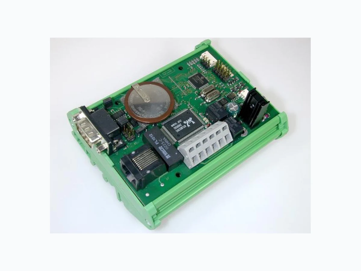
3000-U14-00 AMKA
Document overview
- Manufacturer or author: Provided By www.digicamel.com(free datasheet download site)
- PDF pages: 1
Technical content
Electronic Locking & Monitoring 3000 - U 1 4 - 00 © EMKA Electronic, all rights reserved Rev. 2011-12-05 / Roh-Art.-Nr. 1360 Page 1 of 1 Kommunikationsmodul – Bauform Kit Das Modul 3000 -U14 ist die Zentraleinheit des ELM-Systems. Es verfügt über e inen Ethernet Anschluss und ein en RS232- Anschluss. Der Datenspeicher der U14 enthält die aktuelle Systemkonfiguration. Mit 2 Relaiskontakten k önnen extern Schaltvorgänge ausgelöst werden, die mit der Steuersoftware ELMcontrol Ereignissen im System flexibel zuzuordnen sind. Technische Änderungen vorbehalten. Communications Module – Kit Style The module 3000 -U141-00 is the control and interfa ce module of the ELM system. Ethernet connection and a serial RS232 interface are available. Actual system configuration is stored in the module RAM memory. 2 relay contacts are available for external control functions. Alarms or events can be assigned via control software ELMcontrol to trigger the on -board relays is part of the ELM system. Subject to technical changes. Power supply: 12 VDC, 180 mA; + 10 mA for each LED RAM battery: 3V (VL 3032)#; 1 year retention time with battery fully charged Relay switch data: 30 V DC, max. 1.0 A / 48 V AC, 0.5 A Temp. range: 0 … 60 °C LED TXC: ON for 2 s during initialization; ON for 30 s if RAM is cleared; blinking after successful CAN Bus cycle LED RXC: Blinking when CAN Bus is active, ON when CAN bus is interrupted LED TXN: Network SEND LED COL: Network collision LED 7: Relay 1 enabled LED 9: Relay 2 enabled Dimensions: 107mm x 90mm x 60mm (W x D x H) Fig. 1 3000-U14-00 RS 232 9 pin SubD connector; TTL level on male connector J4; baud rate 38400 bits/s Network RJ 45 jack; 10 MBit Ethernet; Protocol IP CAN Bus JST-S4-ZR edge connector, cable connection via socket terminal strip JST ZHR-4. If the module is the first or the last in the chain then CAN Bus termination switch must be set to “ON”, otherwise “OFF”. This is essential for correct operation! External LED’s LED connectors for TXC, RXC, TXN, RXN und COL are available on edge connector J2. Max. load per output is 13 mA. Clear RAM Open J3 for about 5 sec Note Power supply is fed from another module through CAN Bus connectors CAN1 or CAN2 Fig. 2 Schematic diagram