
3000-U13-02 AMKA
Document overview
- Manufacturer or author: Provided By www.digicamel.com(free datasheet download site)
- PDF pages: 1
Technical content
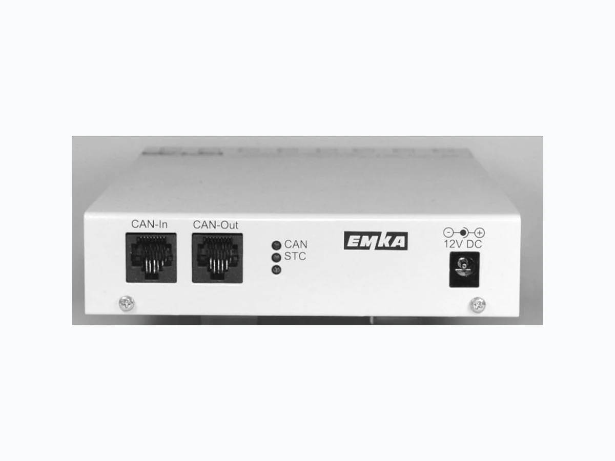
Electronic Locking & Monitoring 3000 - U13 - 02 EMKA Beschlagteile GmbH & Co. KG Rev. 2017-05-12 / Roh Art.-Nr. 1573 Page 1 of 1 Sensor Unit – Bauform Box Das Modul 3000 -U13-02 ist Bestandteil des ELM Systems. Bis zu 4 analoge Sensoren aus dem ELM Programm lassen sich anschließen. Auf dem Modul stehen 4 Relais mit Umschaltkontakten zur Verfügung, deren Sensor-Schwellwerte bei der Systemkonfiguration zugewiesen werden können. Technische Änderungen vorbehalten. Sensor Unit – box style The 3000-U13-02 module is part of the ELM system. Up to 4 analog ELM sensors can be connected. The module provides 4 relays with switch over contacts. Sensor setpoints and alarms can be assigned during system configuration. Subject to technical changes. Power supply: 12 V DC, 140 mA + sensor current (s) Sensor input: 0...7500 mV, 13.3 kΩ, overvoltage protection -25...+30 V Sensor supply: 12 V DC Relay switch data: max. 48 V DC, max. 1.0 A, max. 30 W Relay contact, carrying: max. 2 A, resistance 100 mΩ LED CAN: flashing when active, otherwise ON LED STC: Normally OFF, flashing when module status is changed Fig. 1: 3000-U13-02 front Box dimensions: 135 x 32 x 229 mm (W x H X D) CAN bus wiring The box modules are linked together by RJ45 patch cables. Connect CAN-Out of a module to CAN -In of the next module. Open CAN -In / CAN -Out sockets must be equipped with a termin ating plug for proper operation. Terminating plugs are supplied with the communication module 3000-U14-02 and Control Unit 3000-U141-02. Power supply A 12 VDC, 1000 mA (e.g. 3003-03-02) power supply is required for each sensor unit. From this, power can be fed to other modules – keypads, communication, handle or latch modules, RFID card readers etc. by CAT 5, CAN bus patch cables. Check that the total current requirements do not exceed the rating of the power supply. Addressing Module addressing is done during system configuration. Please refer to manual for communication module 3000-U14-02 or Control Unit 3000-U141-02 for details. Fig. 2: 3000-U13-02 rear Fig. 3: top side label