
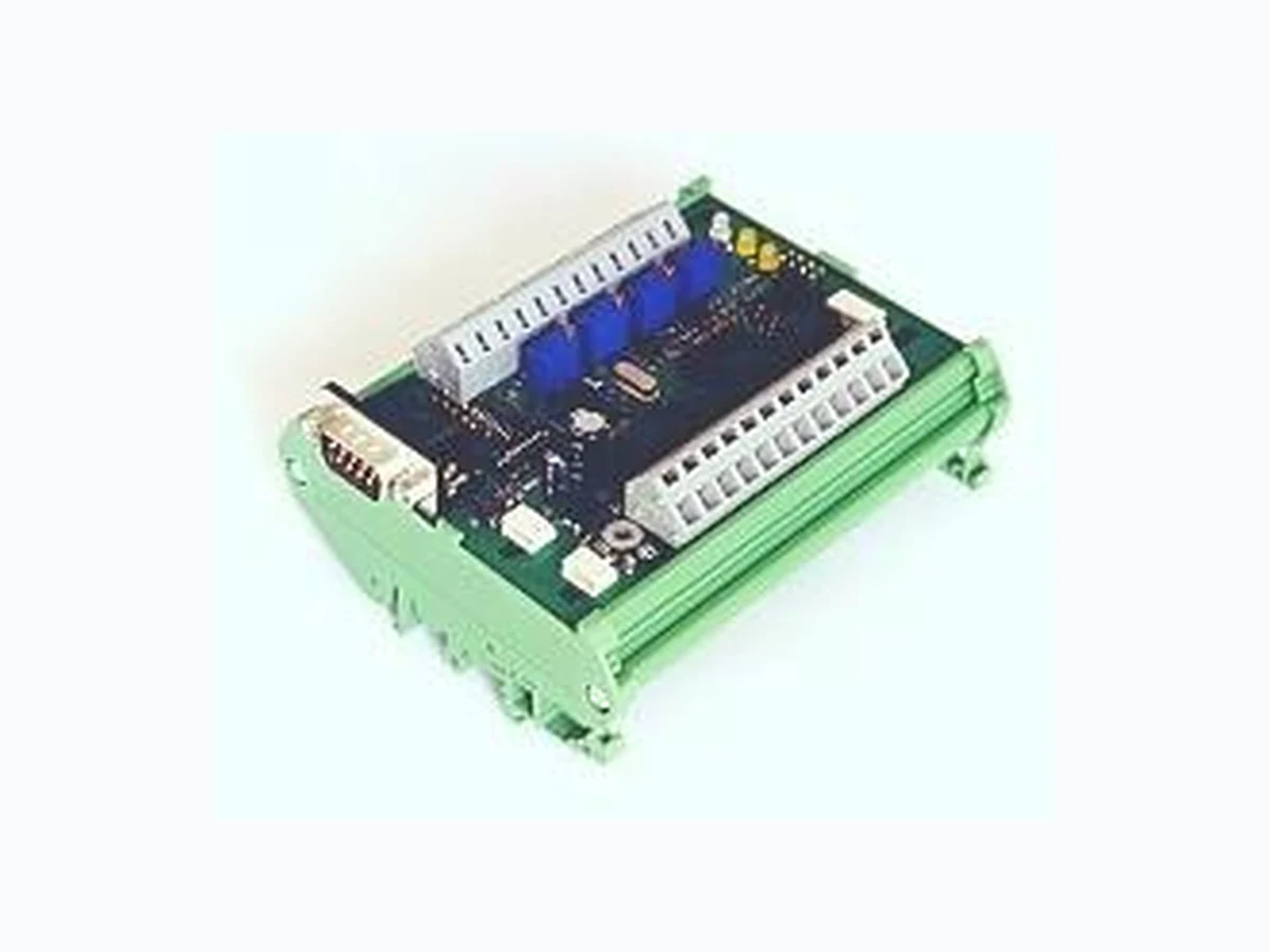
3000-U13-00 AMKA
Document overview
- Manufacturer or author: Provided By www.digicamel.com(free datasheet download site)
- PDF pages: 1
Technical content
Electronic Locking & Monitoring 3000 - U 1 3 - 00 © EMKA Electronic, all rights reserved Rev. 2011-12-06 / Roh-Art.-Nr. 1359 Page 1 of 1 Sensormodul – Bauform Kit Das Modul 3000 -U13-00 ist Bestandteil des ELM Systems. Bis zu 4 analoge Sensoren aus dem ELM Programm lassen sich anschließen. Auf dem Modul stehen 4 Relais mit Umschaltkontakten zur Verfügung, d ie bei Grenzwertverletzungen der Sensoren aktiviert werden können. Die Einstellungen werden über die Konfiguriersoftware ELMcontrol vorgenommen. Technische Änderungen vorbehalten. Sensor Module – Kit Style The 3000-U13-00 module is part of the ELM system. Up to 4 analog ELM sensors can be connected. The module provides 4 relays with switch over contacts. Sensor alarms can be assigned via standard software ELMcontrol Subject to technical changes. Power supply: 12 V DC, 140 mA + sensor current (-s) Sensor input: 0...7500 mV, 13.3 kΩ, overvoltage protection -25...+30 V Sensor supply: 12 V DC Relay switch data: max. 48 V DC, max. 1.0 A, max. 30 W Relay contact, carrying: max. 2 A, resistance 100 mΩ LED CAN: flashing when active, otherwise ON LED STC: Normally OFF, flashing when module status is changed Dimensions: 90 x 50 x 152 mm (W x H X D) Board: H1m13v2e1 Fig. 1: 3000-U13-0 Addressing The module address is assigned by the dip switch. The address is the sum of the address values of switches set to “OFF”. In the example on the left, address is set to “1” (only the switch D/1 is active). Address “3” would mean setting dip switch “D1” and “D/2” to “OFF”. When all 6 address switches are set to “ON” the address is assigned dynamically via software command. CAN Bus If the module is the first or the last in the module chain then the CAN Bus termination switch must be set to “ON”, otherwise “OFF”. This is essential for correct operation! Fig. 2: Schematic diagram Note Power supply is fed from another module through CAN Bus connectors CAN1 or CAN2. Alternatively a power supply can be connected to one of the +12 V and GND terminals of the sensors. In this case a sensor can be added in parallel to this port. CAN 2 J91 CAN 1 J10 RS 232 J10ON Reserved Reserved Reserved D/32 D/16 D/8 D/4 D/2 D/1 1 2 3 4 5 6 7 8 9 10 11 12 +12 V Sens.1 IN Sens.2 IN Sens.3 IN Sens.4 IN 1 2 3 4 5 6 7 8 9 10 11 12 Rel.1 p. Rel.1 o. Rel.1 u. Rel.2 p. Rel.2 o. Rel.2 u. Rel.3 p. Rel.3 o. Rel.3 u. Rel.4 p. Rel.4 o. Rel.4 u. Relay Relay Relay Relay LCAN LSTC PROG CAN bus termination OFF Rel.1 p.: Relay 1 powered Rel.1 o.: Relay 1 switchover Rel.1 u.: Relay 1 unpowered +12 V +12 V +12 V +12 V