
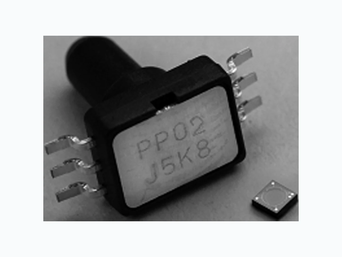
2SMPP_11 OMRON
Document overview
- Manufacturer or author: Provided By digicamel.com
- PDF pages: 10
Technical content
MEMS Gauge Pressure Sensor 2SMPP 35 MEMS Gauge Pressure Sensor 2SMPP MEMS Gauge Pressure Sensor Featuring Small Size and Low Power Consumption
- Ultra-miniature 6.1 × 4.7 × 8.2 mm (L × W × H). Piezo Resistive element provides electrical characteristics that are superior to capacitive type pressure sensors. 0 to 37 kPa (2SMPP-02) or -50 to 50 kPa (2SMPP-03) pressure range. Low Power consumption of 0.2 mW Low Temperature Influence RoHS Compliant
Ordering Information
Standard Models with Surface mount package Terminal Arrangement Application Examples Medical equipment Home appliance Air movement control Level indicators Leak detection Pressure controller Classification Pressure Range Structure Packaging Model Bottom Port Type 0 to 37 kPa SOP Plastic sleeve 2SMPP-02 -50 to 50 kPa 2SMPP-03 Vout (−) Nsub (Connect to ICC) Non Conneted GND Icc Vout (+)
36 MEMS Gauge Pressure Sensor 2SMPP
■Ratings Note: 1. The above values are initial values measured at ambient temperature condition of 23°C. 2. Please avoid caustic gases. 3. Standard 2SMPP-02 product is not calibrated for negative pressures. ■Electrical Characteristics Note: 1. The above values are initial values measured at ambient temperature condition of 23°C. 2. Not including temperature influence. 3. The above values are operated at 100 μADC ■Environment Characteristics Item 2SMPP-02 2SMPP-03 Pressure type Gauge Pressure Sensing type Piezo Resistive Applicable gases Air (Non-corrosive, dust free) Ratings Pressure range 0 to 37 kPa -50 to 50 kPa Withstand pressure Max. 53 kPa -80 to 120 kPa Supply current 100 μADC (130 μADC absolute max.) 100 μADC (200 μADC absolute max.) Ambient operating temperature 0 to 50°C (with no icing or condensation) -10 to 100 °C (with no icing or condensation) Ambient operating humidity 15 to 90%RH (with no icing or condensation) 10 to 95%RH (with no icing or condensation) Ambient storage temperature −30 to 85°C (with no icing or condensation) −40 to 120°C (with no icing or condensation) Ambient storage humidity 10 to 95%RH (with no icing or condensation) Item 2SMPP-02 2SMPP-03 Pressure type Positive Negative Operating pressure range 0 to 37 kPa 0 to 50 kPa -50 to 0 kPa Bridge resistance 20 ± 2 kΩ Offset voltage (See note 2.) −2.5 ± 4.0 mV Hysteresis (See note 2.) 0 ± 0.5%FS (0 to 37 kPa) 0 ± 0.2%FS (-50 to 50 kPa) Temperature influence of Offset 0 ± 3.0%FS (0 to 25°C) -1.0 ± 3.0%FS (at 0°C) Item 2SMPP-02 2SMPP-03 Vibration resistance Destruction 10 Hz to 500 Hz 10 G Malfunction 10 Hz to 500 Hz 10 G Shock resistance Destruction 15 G Malfunction 15 G Life Expectancy 300,000 Operations min. (0 to 39 kPa) 100,000 Operations min. (0 to 75 kPa) ESD 1000 V (Human body model) Weight 0.17 g Package Material PPS (Polyphenylenesulfide)
MEMS Gauge Pressure Sensor 2SMPP 37 Engineering Data (for reference) ■Output Characteristics - 2SMPP-02 Rated Pressure vs. Output Voltage Note: 1. Ambient temperature condition: 25°C 2. Drive current: 100 μA 3. These output voltage characteristics are measured with tester without a mounting board. 4. The output voltage characteristics may be influenced by the mounting board. Be sure to check operation including dura bility in actual equipment before use. Temperature influence of Span voltage T emperature influence of Offset voltage Note: 1. Measured points are 0°C and 25°C, 50°C 2. Drive current: 100 μA 3. These output voltage characteristics are measured with tester without a mounting board. 4. The output voltage characteristics may be influenced by the mounting board. Be sure to check operation including dura bility in actual equipment before use. Rated Pressure [kPa] Output Voltage [mV] 01 0 2 0 3 0 4 0 5 0 Temperature [°C] −1.0 0.0 −0.5 −1 00 1 02 03 04 05 0 6 0 0.5 1.0 1.5 2.0 Temp. Influence of Span Voltage [%FS] Temperature [°C] −2.0 −1.0 −1.5 0.0 −0.5 −1 00 1 02 03 04 05 0 6 0 0.5 1.0 1.5 2.0 Temp. Influence of Offset Voltage [%FS]
38 MEMS Gauge Pressure Sensor 2SMPP
Pressure cycle range (0 to 40 kPa) Note: 1. Tested temperature condition: 25°C 2. Number of pressure cycle time: 3 x 10⁵ 3. Rated cycle pressure: 0 to 40 kPa 4. These output voltage characteristics are measured with tester without a mounting board. ■Output Characteristics - 2SMPP-03 Rated Pressure vs. Output Voltage Note: 1. Ambient temperature condition: 25°C 2. Drive current: 100 μA 3. These output voltage characteristics are measured with tester without a mounting board. 4. The output voltage characteristics may be influenced by the mounting board. Be sure to check operation including dura bility in actual equipment before use. Pressure cycle −0.5 0 100000 200000 300000 0.5 Offset voltage range [%FS] Pressure cycle −0.5 0 100000 200000 300000 0.5 Span voltage range [%FS] 100-10-20-30-40-50 20 30 40 50 -50 -40 -30 -20 -10 Rated Pressure [kPa] Output Voltage [mV]
MEMS Gauge Pressure Sensor 2SMPP 39 Temperature influence of Span voltage (at 50 kPA) Temperature influence of Offset voltage (at 0 kPa) Note: 1. Measured points are 0°C, 25°C, 50°C and 85°C at 0 to 50 kPa. 2. Drive current: 100 μA 3. These output voltage characteristics are measured with tester without a mounting board. 4. The output voltage characteristics may be influenced by the mounting board. Be sure to check operation including dura bility in actual equipment before use. Pressure cycle range (0 to 75 kPa) Note: 1. Tested temperature condition: 25°C 2. Number of pressure cycle time: 1 x 10⁵ 3. Rated cycle pressure: 0 to 75 kPa 4. These output voltage characteristics are measured with tester without a mounting board. Temperature [°C] Temp. Influence of Positive Span Voltage [%FS] -1.0 -0.5 0.0 0.5 1.0 2.0 1.5 0-10 10 20 30 40 50 60 70 809 0 -2.0 -1.5 -1.0 -0.5 0.0 0.5 1.0 1.5 2.0 2.5 3.0 0-10 10 20 30 40 50 60 70 809 0 Temperature [°C] Temp. Influence of Offset Voltage [%FS] -0.5 0.5 0 25000 50000 75000 100000 Pressure cycle Offset voltage range [%FS] Pressure cycle Span voltage range [%FS] -0.5 0.5 0 25000 50000 75000 100000
40 MEMS Gauge Pressure Sensor 2SMPP
Example of application circuit for MEMS Pressure Sensor 1. The pressure sensor is designed to convert a voltage by means of constant current drive. 2. Please amplify the output voltage of the pressure sensor by using the amplifying circuit if necessary. VDD Vout Pressure Sensor Amplifier circuit unit Constant current circuit unit
MEMS Gauge Pressure Sensor 2SMPP 41 Dimensions Note: All units are in millimeters unless otherwise indicated. A 3# 1 PP02 6 7 8 *part will be marked “PP03” for 2SMPP-03 4.75 4.00 9.85 3.20 φ0.62 φ3.80 6.15 5.40 1.27 x 2 = 2.54 1.27 1.00 2.00 1.502.80 4.75 1.00 The tolerance is ±0.3mm unless otherwise specified. (1.10) φ2.60 φ1.80 4-R0.50 0.40 0.25±0.05
6 Icc
5 N-sub
4 Vout (-)
1 Vout (+)
3 GND
5.45 4.05 3.30 1.65 (0.90) 0.90 0.451.125 1.125 1.65 (1.075) LOT NUMBER 0.100.75 Top view 2SMPP-02 2SMPP-03 Marking
42 MEMS Gauge Pressure Sensor 2SMPP
■Precautions for Correct Use Handling
- Only air can be used as pressure media on the products directly. It is prohibited to use pressure media including corrosive gases (e.g. organic solvents gases, sulfur dioxide and hydrogen sulfide gases), fluid and any other foreign materials. The products are not water proof. Please keep dry in use. Don't use the products under de w-condensing conditions. Frozen fluid on sensor chips may also c ause fluctuation of sensor output and other troubles. Don't put foreign materials (e.g. a wire or pin) into connecting tube. It may cause breakage of pressure sensor chips or fluctuation of sensor output caused by clogging the tube. Use the products within rated pr essure. Usage at pressure out of the range may cause breakage. Don't use under high-frequency vibration including ultrasonic wave. The products may be broken by static electricity. Charged materials (e.g. a workbench and a floor) and workers must provide measures against static electricity, including ground connection. Overpowering terminals may deform them and detract their solder- ability. Don't drop or handle the products roughly. Don't use the products under humid or dusty condition. Terminals connection of pressure sensors must be handled as directed by a connection diagram. Environmental Conditions for Transport and Storage It is prohi bited to keep the products with corrosive gases (e.g. organic solvents gases, sulfur dioxide and hydrogen sulfide gases). The products are not water proof. Please keep dry during storage. An anti-static treatment has been applied to the sleeves. Please note the following points. 1. Getting wet may remove an anti-static treatment and elimi- nate its effect. 2. The sleeves may feel sticky under hot and humid condition due to the nature of the anti-static treatment. 3. Anti-static has aging degradation. It is prohi bited to keep the sleeves for more than six months. The sleeves are also non- reusable. Don't keep the products under humid or dusty condition. Mounting Use lands on the printed-circuit boards to which the sensor can be securely fixed. Fix pin No.2 on the printed-circuit boards, not fixed causes fluctua- tion of sensor output signals. Soldering Due to its small size, the thermal capacity of the pressure sensor is low. Therefore, take steps to minimize the effects of external heat. Dip soldering bath: Max.260°C, within 10 sec. Soldering iron: Max. 260°C, within 10 sec. Do not heat the case of sensor package, heat only terminal. Use a non-corrosive resin type of flux. Since the pressure sensor chip is exposed to the atmosphere, do not allow flux to enter inside. Cleaning Since the pressure sensor chip is exposed to atmosphere, do not allow cleaning fluid to enter inside. Avoid ultrasonic cleaning since this may cause breaks or discon- nections in the wiring. Coating Do not coat the pressure sensor when it is mounted to the print cir- cuit board. Do not wash the print circuit board after the pressure sensor is mounted using detergent containing silicone. Otherwise, the deter- gent may remain on the surface of the pressure sensor. ■Definitions 1. Offset voltage is defined as the ouput voltage at 0 kPa rated pressure 2. Positive span voltage is defined as the algebraic difference between the output voltage at 50 kPa rated pressure and and the output voltage at 0 kPa rated pressure. (37 kPa and 0 kPa for 2SMPP-02) 3. Negative span voltage is defined as the algebraic difference between the output voltage at -50 kPa rated pressure and the output voltage at 0 kPa rated pressure. (Not applicable for 2SMPP-02) 4. Hysteresis is defined as follows; {The maximum value of difference at the same pressure}/span voltage x 100 %FS 5. Temperature influence of span voltage is defined as follows; {Span voltage at 0°C - span voltage at 25°C}/span voltage at 25°C x 100%FS {Span voltage at 50°C - span voltage at 25°C}/span voltage at 25°C x 100%FS {Span voltage at 85°C - span voltage at 25°C}/span voltage at 25°C x 100%FS - - - does not apply to 2SMPP-02 6. Temperature influence of offset voltage is defined as follows {Offset voltage at 0°C - offset voltage at 25°C}/span voltage at 25°C x 100%FS {Offset voltage at 50°C - offset voltage at 25°C}/span voltage at 25°C x 100%FS {Offset voltage at 85°C - offset voltage at 25°C}/span voltage at 25°C x 100%FS - - - does not apply to 2SMPP-02
MEMS Gauge Pressure Sensor 2SMPP MEMO
MEMS Gauge Pressure Sensor 2SMPP OMRON ON-LINE Global - http://www.omron.com USA - http://www.components.omron.com Cat. No. X305-E-1b Printed in USA OMRON ELECTRONIC COMPONENTS LLC 55 E. Commerce Drive, Suite B Schaumburg, IL 60173 847-882-2288 11/12 Specifications subject to change without notice All sales are subject to Omron Electronic Components LLC standard terms and conditions of sale, which ALL DIMENSIONS SHOWN ARE IN MILLIMETERS. To convert millimeters into inches, multiply by 0.03937. To convert grams into ounces, multiply by 0.03527.