
DATASHEET SEARCH SITE
Document overview
- Manufacturer or author: Provided By digicamel.com
- PDF pages: 22
Technical content
Digital Barometric Pressure Sensor High accuracy and small size barometric pressure sensor with low current consumption
- Measure barometric pressure and temperature with high accuracy Built in low noise 24 bit ADC Digital control and output via I 2C/SPI interface Automatically power down non-working circuit to minimize power consumption Individual calibration parameters stored in OTP* * One Time Programmable - ROM Application Example
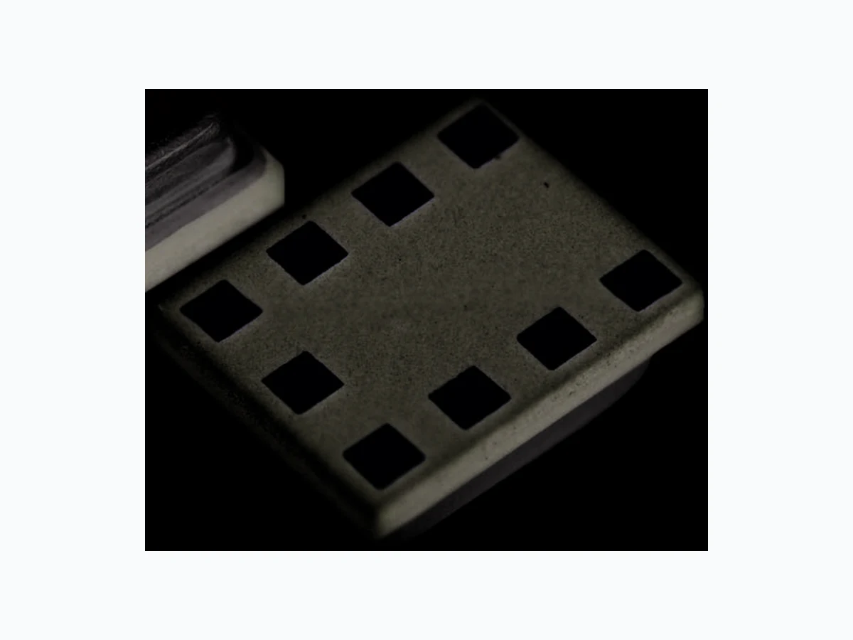
- Indoor navigation (floor detection) Car navigation (to distinguish highway and frontage road) A l t i m e t e r Activity monitor (to detect up and down of stairs) L i f e l o g Weather forecast Target Devices Example Smart Phones / Tablet PCs Wearable devices, such as watch type, band type, clip type or glasses type GPS devices Pedometer Packaging Information ■ Standard Models with Surface Mounting Terminals RoHS compliant Structure Packaging Model Minimum Packing Unit LGA 9 pin Tape and Reel 2SMPB-02B 3,500
2SMPB-02B Digital Barometric Pressure Sensor 2SMPB-02B Table of Contents
2SMPB-02B Digital Barometric Pressure Sensor 2SMPB-02B Ratings / Specifications / Function ■ Use conditions and recommended operating conditions * Never use corrosive gases. ■ Absolute Maximum Ratings ■ Operating Ratings ■ Electrical Characteristics (At Ta = 25°C, VDD = 1.8 V, unless otherwise noted) Note: 1. Typical specifications are not guaranteed. Note: 2. The above table shows the characteristics of the Package before soldering. ■ Digital Interface Characteristics (At Ta = 25°C, VDD = 1.8 V, unless otherwise noted) * “Io” is the load current of the output terminal. Note: Undescribed items are compliant with the I 2C specification. About detailed I2C bus information, please refer to the I2C bus specification and user manual presented by NXP. Type of Pressure Absolute pressure Medium Air * Operating Pressure Range 30 kPa to 110 kPa Item Symbol Rating Unit Remark Power Supply Voltage Vddmax 4.0 V Input Voltage (other than power) Vmax -0.2 to Vopr+0.2 V Maximum Pressure Pmax 800 kPa Storage Temperature Tstr -40 to 85 °C with no condensation or icing Storage Humidity Hstr 10 to 95 %RH with no condensation or icing ESD (HBM) Vhbm ±2000 V ESD (MM) Vmm ±200 V ESD (CDM) Vcdm ±500 V Item Symbol Min. Typ. Max. Unit Remark Operating Voltage Vopr 1.71 1.8 3.6 V VDD Vio 1.20 1.8 3.6 V VDDIO Operating Temperature Topr -40 - 85 °C Item Symbol Condition Min. Typ. Max. Unit Average Current Ihp 1 sample/s Forced Mode Ultra High Accuracy - 21.4 - µA Operating Current Consumption Iddp Pressure mode - 640 800 µA Iddt Temperature mode - 410 520 µA Sleep Mode Current Consumption Isleep - 1.1 2.3 µA Measureable Pressure Range Popr 30 - 110 kPa Absolute Pressure Accuracy Pabs1 90 to 110 kPa, 0 to 40 °C -100 - 100 Pa Relative Pressure Accuracy Pr el1 Ultra High Accuracy - ±3.9 - Pa rms Noise Pnois Ultra High Accuracy - 1.3 - Pa Absolute Temperature Accuracy Tabs 90 to 110 kPa, 0 to 40 °C- 2 - 2 °C Pressure Resolution Pres - 0.06 - Pa Temperature Resolution Tres - 0.0002 - °C Power Supply Rejection Ratio (DC) Ppsrr 101.3 kPa, 0 to 40°C, 1.71 to 3.6 V Base on VDD = 1.8 V -9.4 - 9.4 Pa Item Symbol Condition Min. Typ. Max. Unit Digital Input Low Voltage Vil_d - - Vio×0.2 V Digital Input High Voltage Vih_d Vio×0.8 - Vio+0.2 V Digital Input Hysterisis Voltage Vidhys Vio×0.1 - - V Digital Output Low Voltage (I 2C) Vol_d1 Io = 3 mA (SDI) * 0 - Vio×0.2 V Digital Output Low Voltage (SPI) Vol_d2 Io = 1 mA (SDI, SDO) * 0 - Vio×0.2 V Digital Output High Voltage1 (SPI) (Vio >= 1.62 V) Voh_d1 Io = 1 mA (SDI, SDO) * Vio×0.8 - - V Digital Output High Voltage2 (SPI) (Vio >= 1.2 V) Voh_d2 Io = 1 mA (SDI, SDO) * Vio×0.6 - - V Leakage Current at Output OFF Ioff SDI, SDO -10 - 10 µA Internal Pullup Resistor Rpullup CSB 70 120 190 k Ω I2C Load Capacitance Cb SDI, SCK - - 400 pF Load Capacitance of Reset Terminal Crst - - 20 pF Pulse Width of Asynchronous Reset Trst 100 - - µsec Power On Startup Time Tstart - - 10 msec
2SMPB-02B Digital Barometric Pressure Sensor 2SMPB-02B ■ Characteristics by Oversampling setting (Forced Mode) (At Ta = 25°C, VDD = 1.8 V, CPU Clock Frequency = 300 kHz, unless otherwise noted) Note 1: These characteristic s are guaranteed by design. Note 2: ODR is defined as Output da ta rate at standby time 1 msec. ■ rms Noise by IIR Filter Selection (At Ta = 25°C, VDD = 1.8 V, unless otherwise noted) Note 1: IIR; Infinite impulse response Note 2: These characteristic s are guaranteed by design. Note 3: Initial setting of the II R filter coefficient is “off”. ■ Bandwidth by IIR Filter Selection (At Ta = 25°C, VDD = 1.8 V, unless otherwise noted) Note 1: These characteristic s are guaranteed by design. Note 2: Initial setting of the II R filter coefficient is “off”. ■ Filter selection based on use cases (At Ta = 25°C, VDD = 1.8 V, unless otherwise noted) Note: These characteristics are guaranteed by design. Oversampling setting Pressure oversampling Temperature oversampling Measurement time Typ. ODR @ standby 1 ms Typ. Average Current Typ. @ 1 sample/sec Forced Mode rms Noise Typ. unit - - msec Hz µA Pa High speed 2 1 5.5 153 4.1 5.2 Low power 4 1 7.2 121 5.2 3.7 Standard 8 1 10.6 86 7.3 2.6 High accuracy 16 2 18.3 51 12.0 1.8 Ultra High accuracy 32 4 33.7 28 21.4 1.3 Oversampling setting Typical rms Noise in Pressure [Pa] IIR filter coefficient off 2 4 8 16 32 Oversampling setting Typical Bandwidth [Hz] IIR filter coefficient off 2 4 8 16 32 sampling times Temp. over sampling times Specification (Typ.) IIR filter coefficient Current consumption [µA] ODR [Hz] (Example) rms Noise [Pa] Weather monitoring High speed ×2 ×1 off 1.2 0.05 5.2 Drop detection Low power ×4 ×1 off 407 100 3.7 Elevator detection Standard ×8 ×1 4 63.4 10 0.8 Stair detection High accuracy ×16 ×2 8 219 20 0.4 Indoor navigation Ultra high accuracy ×32 ×4 32 570 28 0.2
2SMPB-02B Digital Barometric Pressure Sensor 2SMPB-02B Connection ■ Block Diagram ■ Pin Description and Layout *1. If you do not need the reset function, please just have the layout design of PCB of connecting both No. 1 (RST) pin and No. 7 (GND) pin into the ground of PCB. Please refer “■Reset Function” for the case of using the reset function. *2. Pin 9 is only used internally in OMRON. Please leave the pin disconnected. If Pin 9 is connected with any other Pin electrically, the sensor will not work properly. Pin No. Symbol
Description
1 RST Asynchronous Reset *1
2 CSB CSB VDDIO
3 SDI SDI/SDO SDA
4 SCK SCK SCL
5 SDO SDO ADDR
6 VDDIO Power Terminal for Digital IO
7 GND Ground Terminal
8 VDD Power Terminal
9 VPP NVM Writing Terminal *2
CLK Gen. POR NVM MUX Analog front-end GND Pin 1 indicator Bottom ViewTop View 1 9 8 2 7 3 6 4 5 8 9 1 7 2 6 3 5 4
2SMPB-02B Digital Barometric Pressure Sensor 2SMPB-02B ■ Typical Connection Diagram I2C mode (Corresponding to 100 Kbit/s (at Standard Mode), 400 Kbit/s (at Fast Mode) and 3.4 Mbit/s (at High Speed Mode)) 4-wire SPI mode (Corresponding to 10 Mbit/s) 3-wire SPI mode (Corresponding to 10 Mbit/s) CSBGND VDDIO VPP RST VDD 8 9 1 7 2 2SMPB-02B Top View SDI SDO SCK 5 4 Slave address SEL (gnd or VDDIO) 1 µF RST SDA SCL VDDIO VDD 1 µF CSBGND VDDIO VPP RST VDD 8 9 1 7 2 2SMPB-02B Top View SDI SDO SCK 5 4 SDO 1 µF RST SDI SCK VDDIO VDD 1 µF CSB CSBGND VDDIO VPP RST VDD 8 9 1 7 2 2SMPB-02B Top View SDI SDO SCK 5 4 1 µF RST SDI/SDO SCK VDDIO VDD 1 µF CSB
2SMPB-02B Digital Barometric Pressure Sensor 2SMPB-02B Dimensions (Unit: mm) ■ Package Package Type: LGA (Land Grid Array) 9 pin Package Size: 2.00 × 2.50 × 0.85 mm Material of the terminal surface: Au ■ Outline Dimension ■ Mounting PAD Dimensions Recommended (Top View) ■ Marking structure 2.00±0.10 2.50±0.10 0.71±0.05 0.46±0.05 0.35 2.17 2.32±0.03 0.85±0.10 1.67 1.82±0.03 2-P0.65×3=1.95 5-(0.10) 9-0.35 8- 0.10 9-0.35 1.45 0.20±0.05 dia. 0.55 0.50 0.10 0.35 2.00 2.50
0.65 PITCH
2SMPB-02B Digital Barometric Pressure Sensor 2SMPB-02B Operations ■ Communication Mode This sensor is corresponding to I2C and SPI communication. Digital interface terminal functions for each communication mode are as below. When changing the communication mode, also see Typical Connection Diagram section. I 2C mode becomes effective by pulling CSB up to VDDIO. SPI mode becomes effective by pulling CSB down to GND. Once CSB is pulled down, SPI mode would not be changed unle ss otherwise Power on Reset (POR) or Asynchronous Reset. Switching between SPI 3-Wire mode and SPI 4-Wire mode can be configured with the register value of “spi3w”. Refer to IO_SETUP register section for more detail. Default mode after POR or Asynchronous Reset will be I2C mode. ■ Power Mode This sensor has three power modes and it can be switched by setting CTRL_MEAS register. Refer to the “CTRL_MEAS” register section for more detail. S l e e p M o d e Normal Mode Forced Mode Transition diagram for each mode is as follows. Sleep Mode (Power Reduction Mode) No measurements are performed. I2C/SPI interface and each register can be accessed even if the sensor is in Sleep Mode. Forced Mode In case of Forced Mode, a single measurement is performed. When the set up measurement is finished, the sensor returns to Sleep Mode after storing the measurement data to the register. Normal Mode In case of Normal Mode, the measurements are performed repeatedly between a measurement period and a standby period. The standby time can be configured by “t_stanby[2:0]” register. Be sure to consider that the data must be read from the master side after a Normal Mode. Communication Mode CSB SDI SCK SDO Remark I2C VDDIO SDA SCL GND/VDDIO SDO = GND → 70h, SDO = VDDIO → 56h SPI 3 Wires CSB SDI/O SCK - spi3w Register = 1 SPI 4 Wires CSB SDI SCK SDO spi3w Register = 0 Power_mode[1:0]=11 Power_mode[1:0]=00 Power_mode[1:0]=01 or 10 Power_mode[1:0]=01 or 10 POR Power ON Down load OTP Normal Mode Sleep Mode Asynchronous Reset (Reset [ 7 : 0 ] = E6h) Forced Mode Read COE_ po wer_mode[1:0] = 01 or 10 power_mode[1:0] = 01 or 10 Power On Read COE_ po wer_mode[1:0] = 11 t_stanby[s] Power On
2SMPB-02B Digital Barometric Pressure Sensor 2SMPB-02B ■ Compensation of Pressure and Temperature This section describes a typical measurement procedure and a calc ulation method after POR. This sensor has compensation coeffi- cients in internal Non Volatile Memory (NVM). The compensated pressure can be calculated by using these values. MSB of PRESS_TXDx, TEMP_TXDx and COE_ are sign bit. (1) Configure IO mode setting. Refer to IO_SETUP register section for more detail. (2) Read compensation coefficients which are stored in NVM. This procedure is sufficient just once after POR. These values are used for a compensation calculation at the step (6) and (7). (3) Configure averaging times and power mode. Refer to CTRL_MEAS register section for more detail. (4) Read raw temperature data which are stored in TEMP_TXDx registers. (5) Read raw pressure data which are stored in PRESS_TXDx registers. (6) Compensated temperature can be calculated by using the below formula and the values of the step (2) and (4). Tr : Calculation Result of Temperature ( Tr/256 = Temperature [degree C] ) e.g.) If Tr Value is 6400 LSB, Dt : Raw Temperature Data [digit] ( 22-24bits measurement value of TEMP_TXDx Reg. ) aa : Compensation Coefficient of PTAT ( Coefficient made from COE_PTAT31 and COE_PTAT32 Reg. ) ba : Compensation Coefficient of PTAT ( Coefficient made from COE_PTAT21 and COE_PTAT22 Reg. ) ca : Compensation Coefficient of PTAT ( Coefficient made from COE_PTAT11, COE_PTAT12 and COE_PTAT13 Reg. ) : Read/Write Values through Digital I/F : Calculation by User MCU START (1) Configure IO mode setting by “IO_SETUP” register (2) Read Compensation Coefficients from NVM (COE_) (3) Configure Averaging Times and Power Mode (4) Read Uncompensated Temperature Value (TEMP_TXDx) (5) Read Uncompensated Pressure Value (PRESS_TXDx) (6) Compensate Temperature Value (7) Compensate Pressure Value Tr = 2aa - ba - ba2 - 4aa (ca - Dt)
256 LSB/degree C
6400 LSB
Tr Value (LSB) Temperature (degree C) = = 25.00 degree C=
2SMPB-02B Digital Barometric Pressure Sensor 2SMPB-02B (7)Correction pressure without temperature compensation can be calculated by using the below formula and the values of the step (2 ) and (5). Pl : Calculation result of Pressure [Pa] Dp : Raw Pressure Data [digit] ( 22-24bits measurement value of PRESS_TXDx Reg. ) ap : Compensation Coefficient of Pressure ( Coeffi cient made from COE_PR31 and COE_PR32 Reg. ) bp : Compensation Coefficient of Pressure ( Coeffi cient made from COE_PR21 and COE_PR22 Reg. ) cp : Compensation Coefficient of Pressure ( Coefficient made from COE_PR11, COE_PR12 and COE_PR13 Reg. ) The compensated pressure for temperature can be calculated by using the below formula and the results of step (3), (6) and (7) . Po : Final compensated Pressure. This result is an absolute pressure value. [Pa] at : Compensation Coefficient of Temperature ( Coeffi cient made from COE_TEMP31 and COE_TEMP32 Reg. ) bt : Compensation Coefficient of Temperature ( Coeffi cient made from COE_TEMP21 and COE_TEMP22 Reg. ) ct : Compensation Coefficient of Temperature ( Coeffi cient made from COE_TEMP11 and COE_TEMP12 Reg. ) How to get compensation coefficients Each compensation coefficients (ap, bp, at, bt, ct, aa, ba) can be calculated by using the below formula and conversion factors. The other coefficients (cp, ca) are 24 bits offset value, so raw digit stored in registers can be used. K Conversion factor OTP A S 23-16 bit 15-8 bit 7-0 bit aa 0.00E+00 4.20E-04 COE_PTAT31 COE_PTAT32 ba -1.60E+02 8.00E+00 COE_PTAT21 COE_PTAT22 ca Offset value with 24 bits length COE_PTAT11 COE_PTAT12 COE_PTAT13 ap 0.00E+00 3.00E-05 COE_PR31 COE_PR32 bp 3.00E+01 1.00E+01 COE_PR21 COE_PR22 cp Offset value with 24 bits length COE_PR11 COE_PR12 COE_PR13 at 0.00E+00 8.00E-11 COE_TEMP31 COE_TEMP32 bt -6.60E-06 1.60E-06 COE_TEMP21 COE_TEMP22 ct 4.00E-02 8.50E-03 COE_TEMP11 COE_TEMP12 Pl = 2ap - bp + bp2 - 4ap (cp - Dp) Po = Pl at × Tr 2 + bt × Tr + (ct + 1) K = A + S × OTP 32767
2SMPB-02B Digital Barometric Pressure Sensor 2SMPB-02B ■ Implementing Register List * MSB of PRESS_TXDx, TEMP_TXDx and COE_** are sign bit. Register Name Address R/W Data Descriptions Initial I2C SPI bit7 bit6 bit5 bit4 bit3 bit2 bit1 bit0 TEMP_TXD0 FCh 7Ch R/- t_txd0[7:0] Temperature DATA [8:1] in 24 bits 00h TEMP_TXD1 FBh 7Bh R/- t_txd1[7:0] Temperature DATA [16:9] in 24 bits 00h TEMP_TXD2 FAh 7Ah R/- t_txd2[7:0] Temperature DATA [24:17] in 24 bits * 00h PRESS_TXD0 F9h 79h R/- p_txd0[7:0] Pressure DATA [8:1] in 24 bits 00h PRESS_TXD1 F8h 78h R/- p_txd1[7:0] Pressure DATA [16:9] in 24 bits 00h PRESS_TXD2 F7h 77h R/- p_txd2[7:0] Pressure DATA [24:17] in 24 bits * 00h IO_SETUP F5h 75h R/W t_stanby[2:0] - spi3_sdim -s p i 3 w t_stanby[2:0] : Standby time setting spi3w : SPI mode setting (4 or 3 wire) spi3_sdim : Select output type of SDI terminal 00h CTRL_MEAS F4h 74h R/W temp_average[2:0] press_average[2:0] power_mode[1:0] temp_average[2:0] : Temperature Averaging Times press_average[2:0] : Pressure Averaging Times power_mode[1:0] : Power mode setting 00h DEVICE_STAT F3h 73h R/- - - - - measure - - otp_update measure : Status of measurement otp_update : Status of OTP data access 00h I2C_SET F2h 72h R/W - - - - - master_code[2:0] Master code setting at I 2C HS mode 01h IIR_CNT F1h 71h R/W - - - - - filter[2:0] IIR filter co-efficient setting 00h RESET E0h 60h -/W reset[7:0] When inputting "E6h", a software reset will be occurred. 00h CHIP_ID D1h 51h R/- chip_id[7:0] CHIP_ID1 : 5C 5Ch COE_PTAT32 B4h 34h R/- coe_ptat32[7:0] Compensation Coefficient – COE_PTAT31 B3h 33h R/- coe_ptat31[7:0] Compensation Coefficient * – COE_PTAT22 B2h 32h R/- coe_ptat22[7:0] Compensation Coefficient – COE_PTAT21 B1h 31h R/- coe_ptat21[7:0] Compensation Coefficient * – COE_PTAT13 AFh 2Fh R/- coe_ptat13[7:0] Compensation Coefficient – COE_PTAT12 AEh 2Eh R/- coe_ptat12[7:0] Compensation Coefficient – COE_PTAT11 ADh 2Dh R/- coe_ptat11[7:0] Compensation Coefficient * – COE_TEMP32 ACh 2Ch R/- coe_temp32[7:0] Compensation Coefficient – COE_TEMP31 ABh 2Bh R/- coe_temp31[7:0] Compensation Coefficient * – COE_TEMP22 AAh 2Ah R/- coe_temp22[7:0] Compensation Coefficient – COE_TEMP21 A9h 29h R/- coe_temp21[7:0] Compensation Coefficient * – COE_TEMP12 A8h 28h R/- coe_temp12[7:0] Compensation Coefficient – COE_TEMP11 A7h 27h R/- coe_temp11[7:0] Compensation Coefficient * – COE_PR32 A6h 26h R/- coe_pr32[7:0] Compensation Coefficient – COE_PR31 A5h 25h R/- coe_pr31[7:0] Compensation Coefficient * – COE_PR22 A4h 24h R/- coe_pr22[7:0] Compensation Coefficient – COE_PR21 A3h 23h R/- coe_pr21[7:0] Compensation Coefficient * – COE_PR13 A2h 22h R/- coe_pr13[7:0] Compensation Coefficient – COE_PR12 A1h 21h R/- coe_pr12[7:0] Compensation Coefficient – COE_PR11 A0h 20h R/- coe_pr11[7:0] Compensation Coefficient * –
2SMPB-02B Digital Barometric Pressure Sensor 2SMPB-02B TEMP(PRESS)_TXDx : Temperature and Pressure data : TXD0, TXD1 or TXD2 This sensor holds ADC data with 22 to 24 bits accuracy. It can be obtained as each 24 bits data. If there are redundant data, t he low order positions will be filled by zero (0). The shaded regions as shown below are valid data area. Note: 1. Dn (D23 to D0) : Sensor Data ……The value of n bit (1 or 0) Note: 2. The raw measurement values are unsigned 24 bi ts values. The values need to do subtraction with 223 at 24 bits output mode. Here is a programing example for Dt and Dp calculation. Dt = ((TEMP_TXD2) <<16) + ((TEMP_TXD1) << 8) + (TEMP_TXD0) - pow(2,23) Dp = ((PRESS_TXD2) <<16) + ((PRESS_TXD1) << 8) + (PRESS_TXD0) - pow(2,23) IO_SETUP : IO SETUP Register it7 to 5 t_stanby[2:0] : Standby time setting bit3 to 4 Reserved : keep these bits at 0 bit2 spi3_sdim : Select output type of SDI terminal 0 : Lo / Hi-z output (Default) 1 : Lo / Hi output bit1 Reserved : keep this bit at 0 bit0 spi3w : Change mode between SPI 4-wire and SPI 3-wire 0 : 4-wire (Default) 1 : 3-wire CTRL_MEAS : Measurement Condition Control Register bit7 to 5 temp_average[2:0] Averaging times setting for Temperature measurement (skip means no measurement.) bit4 to 2 press_average[2:0] Averaging times setting for Pressure measurement (skip means no measurement.) bit1, 0 power_mode[1:0] Operation mode setting 00 : Sleep Mode 01, 10 : Forced Mode 11 : Normal Mode DEVICE_STAT : Device Status Register bit7 to 4 Reserved : keep these bits at 0 bit3 measure Device operation status. This value automatically changes. 0: Finish a measurement -- waiting for next measurement 1: On a measurement -- waiting for finishing the data store bit2, 1 Reserved : keep these bits at 0 bit0 otp_update The status of NVM data access. This value automatically changes. 0: No accessing NVM data 1: While accessing NVM data bit 24 23 22 ... 5 4 3 2 1 Note 22 bits output D21 D20 D19 ... D2 D1 D0 0 0 Temp/Press_ave = 001 23 bits output D22 D21 D20 ... D3 D2 D1 D0 0 Temp/Press_ave = 010 24 bits output D23 D22 D21 ... D4 D3 D2 D1 D0 Temp/Press_ave = 011 to 111 Register Name I2C Addr. SPI Addr. Length R/W bit7 bit6 bit5 bit4 bit3 bit2 bit1 bit0 initial IO_SETUP F5h 75h 8bits R/W t_stanby[2:0] – – spi3_sdim – spi3w 00h 000 001 010 011 100 101 110 111 1 ms 5 ms 50 ms 250 ms 500 ms 1 s 2 s 4 s Register Name I2C Addr. SPI Addr. Length R/W bit7 bit6 bit5 bit4 bit3 bit2 bit1 bit0 initial CTRL_MEAS F4h 74h 8bits R/W temp_average[2:0] press_average[2:0] power_mode[1:0] 00h 000 001 010 011 100 101 110 111 s k i p 1248 1 6 3 2 6 4 000 001 010 011 100 101 110 111 s k i p 1248 1 6 3 2 6 4 Register Name I2C Addr. SPI Addr. Length R/W bit7 bit6 bit5 bit4 bit3 bit2 bit1 bit0 initial DEVICE_STAT F3h 73h 8bits R – – – – measure – – otp_update 00h
2SMPB-02B Digital Barometric Pressure Sensor 2SMPB-02B I2C_SET : Master code setting bit7 to 3 Reserved : keep these bits at 0 bit2, 1, 0 master_code[2:0] Master code setting at I 2C high-speed mode. IIR_CNT : IIR filter co-efficient setting Register bit7 to 3 Reserved : keep these bits at 0 bit2, 1, 0 filter[2:0] IIR filter co-efficient setting Write access to this register address, IIR filter will be initialized. Note: Initial setting of the IIR filter coefficient is “off”. RESET : Reset Control Register bit7 to 0 reset[7:0] When input "E6h", the software reset will be effective. Except for that, nothing is to happen. CHIP_ID : Chip ID Confirmation Register bit7 to 0 chip_id[7:0] 5Ch Register Name I2C Addr. SPI Addr. Length R/W bit7 bit6 bit5 bit4 bit3 bit2 bit1 bit0 initial I2C_SET F2h 72h 8bits R/W – – – – – master_code[2:0] 01h 000 001 010 011 100 101 110 111 08h 09h 0Ah 0Bh 0Ch 0Dh 0Eh 0Fh Register Name I2C Addr. SPI Addr. Length R/W bit7 bit6 bit5 bit4 bit3 bit2 bit1 bit0 initial IIR_CNT F1h 71h 8bits R/W – – – – – filter[2:0] 00h 000 001 010 011 100 101 110 111 OFF N = 2 N = 4 N = 8 N = 16 N = 32 N = 32 N = 32 Register Name I2C Addr. SPI Addr. Length R/W bit7 bit6 bit5 bit4 bit3 bit2 bit1 bit0 initial RESET E0h 60h 8bits W reset[7:0] 00h Register Name I2C Addr. SPI Addr. Length R/W bit7 bit6 bit5 bit4 bit3 bit2 bit1 bit0 initial CHIP_ID D1h 51h 8bits R chip_id[7:0] 5Ch 1/N N-1 Z-1 IN OUT
2SMPB-02B Digital Barometric Pressure Sensor 2SMPB-02B ■ I2C Protocol (1) I2C Slave Address The 2SMPB-02 module I2C slave address is shown below. For example, in case of SDO = Low (0), Write Access : Please set LSB of slave address as "0", then the address is E0h (1110_0000b). (70h<<1+WR(0)) Read Access : Please set LSB of slave address as "1", then the address is E1h (1110_0001b). (70h<<1+RD(1)) (2) I2C Access Protocol Examples (3) Register Write Access Protocol After the START condition, a Device Address is sent. This address is seven bits long followed by an eighth bit which is a data direction bit. A 'zero' indicates a transmission "WRITE". After that, the register address and the writing data shall be one set and it s hould be continuously transmitted until a STOP condition. A data transfer is always terminated by a STOP condition generated by the master. (4) Register Read Access Protocol After a START condition, the Device Address with WRITE sign ("0") and Word Address intended to read a first data are transmitte d. Next, "STOP-START" or "Re-START" condition are transmitted by the master. After that, Device Address with READ sign ("1") is trans- mitted by the master. Then, the slave will output the first data that is intended to read. In case of incrementing Register Add ress auto- matically, the slave will output the data repeatedly until NACK is input by the master. If Register Address becomes "FFh", plea se continue to output "00h". Below example shows 3 bytes reading method from "FAh" register. SDO I2C Slave Address (7 bits) Bit bit7 bit6 bit5 bit4 bit3 bit2 bit1 bit0 Add[6] Add[5] Add[4] Add[3] Add[2] Add[1] Add[0] R/W High (1) 56h + R/W Value 1 0 1 0 1 1 0 1/0 Low (0) 70h + R/W Value 1 1 1 0 0 0 0 1/0 Symbol Condition START START condition STOP STOP condition SACK Acknowledge by Slave MACK Acknowledge by Master MNACK Not Acknowledge by Master 76543210 76543210 Black characters: Master --> Sla ve / Blue characters: Sla ve --> Master Start De vice Address 0 SACK 76543210 Register Address SACK Write Data SACK Register Address SACK Write Data SACK SACK Stop--- --- SCL SDA 76543210 76543210 7 6543210 76543210 Read Data of "FBh" MACK Read Data of "FCh" MNACK Stop Start Device Address 0 SACK Register Address "FAh" SACK Start Device Address 1 SACK Read Data of "FAh" MACK 7 6543210 76543210 SCL SDA 7 6543210 76543210
2SMPB-02B Digital Barometric Pressure Sensor 2SMPB-02B ■ SPI Protocol (1) SPI write "SPI Write" needs to transmit the one set data of Register Address (Ctl.="0"+Address) and a writing data in the situation where CSB is "L". Two or more writing can be possible during CSB is "L". If CSB becomes "H", SPI communication will finish. (as well as I2C write) (2) SPI read First, "SPI read" needs to transmit Register Address (Ctl.="1"+Address) in a situation where CSB is "L". Next, the data of the requested register address will be output from SDO. (in case of 3-wire mode, the data will be output from SDI). After that, the register address is automatically incremented by one until CSB becomes "H", the device will output the data rep eatedly. (as well as I2C read) Below shows an example of the 2 bytes reading from "FAh" register. ■ Interface specifications (1) I2C timings All timings apply to 100 kbps (at Standard Mode), 400 kbps (at Fast Mode) and 3.4 Mbps (at High Speed Mode). For I2C timings, the following abbreviations are used : S&F Mode = Standard and Fast Mode Cb = bus capacitance on SDI line HS Mode = High Speed Mode All other naming refers to I 2C specification 2.1 (January 2000). Undescribed items and symbols are compliant with the I2C specification. Items Symbol Condition Min. Typ. Max. Units Remark SDI setup time t SUDAT S&F Mode 160 – – ns HS Mode Vio = 1.62 V 30 – – ns HS Mode Vio = 1.2 V 55 – – ns SDI hold time t HDDAT S&F Mode, Cb ≤ 100 pF 80 – – ns S&F Mode, Cb ≤ 400 pF 90 – – ns HS Mode, Cb ≤ 100 pF Vio = 1.62 V 18 – 115 ns Vio = 1.2 V 25 – 140 ns HS Mode, Cb ≤ 400 pF Vio = 1.62 V 24 – 150 ns Vio = 1.2 V 45 – 170 ns SCK low pulse t LOW HS Mode, Cb ≤ 100 pF Vio = 1.62 V 160 – – ns Vio = 1.2 V 210 – – ns Start 0 Address (7 bit) Write Data (8bit) 0 Address (7 bit) Write Data (8bit) Stop - - - - - - - - - - - - - - - - - - CSB SCK SDI/O Start 1 Address"7Ah"(7 bit) Read Data of "7Ah" Read Data of "7Bh" Stop - - - - - - - - - CSB SCK SDI/O tHDSTA tSUSTA tSUSTO tr SDA SCL SDA tBUF tLOW tf tHIGHtHDDAT tSUDAT
2SMPB-02B Digital Barometric Pressure Sensor 2SMPB-02B (2) SPI timings All timings are applied both to 4-wire and 3-wire SPI. To reduce external noise in High-Z state, we recommend the following; In 4-wire mode, SDO terminal is pulled up to Vio via the resister. In 3-wire mode, SDI terminal is pulled up to Vio via the resister. ■ Reset Function The sensor is capable of resetting the operation with “Asynchronous Reset Terminal (RST pin)”. The procedure is as follows: Input high voltage to RST pin. (100 µs ≥) Turn off (input low voltage) and wait 10 ms. Reset sequence ■ Recommended conditions of communication In case that this sensor and other sensors are connected with a common bus line, if you use this sensor at a communication speed more than 400 kbit/s, after finishing the communication with other sensors, we recommend to provide 1 ms or more waiting time before starting the communication with this sensor in order to ensure a stable communication (see diagram below). Typical connection diagram E xample of communication Items Symbol Condition Min. Typ. Max. Units Remark SCK frequency f_spi – – 10 MHz SCK low pulse t_low_sck 40 – – ns SCK high pulse t_high_sck 40 – – ns SDI setup time t_setup_sdi 20 – – ns SDI hold time t_hold_sdi 20 – – ns SDO output delay t_delay_sdo Cb = 25 pF , Vio = 1.62 V min – – 30 ns Cb = 25 pF , Vio = 1.2 V min – – 40 ns CSB setup time t_setup_csb 40 – – ns CSB hold time t_hold_csb 40 – – ns CSB_HI time t_csb_hi 100 – – ns t_setup_csb CSB SCK SDI SDO t_high_sck t_hold_cs bt_low_sck t_csb_hi t_setup_sdi t_hold_sdi t_delay_sdo Voh_d1orVoh_d2 Vol_d2 MSB IN LSB OUT LSB IN VDD/VDDIO RST Logic reset IO state resetPOR disable disa bleenable ena ble 10 ms 10 ms 100 µs 0 s ≥ MCU 2SMPB -02B Sensor A Sensor B 2SMPB -02B Sensor A Sensor B Sensor A time 1 msec ≥
2SMPB-02B Digital Barometric Pressure Sensor 2SMPB-02B Packaging ■ Configuration of shipment Note: Specification of taping & reel comply with JIS C 0806-3 (IEC 60286-3). ■ Taping Emboss pitch 4 mm type & tape width 8 mm type. Packaging Embossed Carrier Tape Quantity 3,500 pcs / 1 reel 1 reel / 1 Interior box Max. 20 Interior boxes / 1 exterior box Reel 180 mm dia. Insert method see below Symbol Rating W 8.0 +0.03/-0.1 E1 1.75 +/-0.1 F 3.50 +/-0.05 P0 4.0 +/-0.1 P1 4.0 +/-0.1 P2 2.00 +/-0.05 AA G 0.1 2.45 2.95 2.85±0.05 W F B B A-A cross-section B-B cross-section 1.5+0.1 dia. 0 1.05±0.05 dia. 2.35±0.05 1.14±0.05 0.20±0.05 Count Mark Marked every 10 pockets Trailer (no Sensor) > 160 mm Pin 1 indicator Embossed Carrier Tape Sensor housing unit Leader (no Sensor) > 400 mm No Sensor unit > 100 mm Cover Tape Direction to pull out
2SMPB-02B Digital Barometric Pressure Sensor 2SMPB-02B ■ Reel ■ Individual packaging Reel 180 mm dia. comply with JIS C 0806-3 requirements Direction to pull out Label Aluminium-laminated bag Label Aluminium-laminated bag Reel Label
2SMPB-02B Digital Barometric Pressure Sensor 2SMPB-02B Recommended Soldering Method ■ Soldering method Air Reflow ( Max. 2 times) ■ Condition of Temperature Max. 260°C, within 40 seconds ■ Recommended Soldering Method Temperature profile conditions of reflow soldering should set the temperature condition as shown in the below table and then confirm that actual conditions are met them in the table. Since the pressure sensor chip is exposed to atmosphere, cleaning fluid shall not be allowed to enter inside the sensor's case . We recommend that it should be used the recommended mounting PAD dimensions for the land pattern. Item Preheating (T1 to T2, t1) Soldering (T3, t2) Peak value (T4) Ter minal 150°C to 200°C 60 sec to 180 sec. > 217°C 60 sec to 150 sec. 260°C 20 sec to 40 sec. Soldering Preheating Time (s) Temperature (°C)
2SMPB-02B Digital Barometric Pressure Sensor 2SMPB-02B Safety Precautions Handling (1) Only air can be used as pressure media on the product directly. It is prohibited to use pressure media including corrosive gases (e.g. organic solvents gases, sulfur dioxide and hydrogen sulfide gases), fluid and any other foreign materials. (2) The products are not water proof. The product shall be kept dry in use excluding the sensor port. (3) The product shall not be used under dew-condensing conditions. Frozen fluid on sensor chips may cause fluctuation of sensor out - put and other troubles. (4) The product shall be used within rated pressure. Usage at pressure out of the range may cause breakage. (5) The product may be damaged by static electricity. Charged materials (e.g. a workbench and a floor) and workers should provide measures against static electricity, including ground connection. (6) The product shall not be dropped and handled roughly. (7) The product shall not be used under dusty or damp condition. (8) Do not wash the print circuit board after the pressure sensor is mounted using solvent. It may cause a mal-function. (9) Please connect the sensor terminals according to the connection diagram. (10) The product shall not be used under high-frequency vibration including ultrasonic wave. (11) This product uses the elastic adhesive for bonding the lid, so do not add excessive stress to the lid. (12) If soldering is not fit, then this product may catch fire or get hot. (13) There is a possibility that the peripheral circuit board or some electronic part generates heat while driving this product. Ple ase han- dle with care. (14) Do not tear down this product. (15) Please do not use the sensor after following case; - excessive shock added to the terminal of the sensor - the sensor lid decapped - the sensor dropped (16) If you use other conditions described in this document, please check yourself in advance. Environmental conditions for transport and storage (1) The product shall not be kept with corrosive gases (e.g. organic solvents gases, sulfur dioxide and hydrogen sulfide gases). (2) The products are not water proof. The product shall be kept dry during storage. (3) The outer box strength may be degraded depending on the storage conditions. Please use the product in order. (4) For this product, please keep away from direct sunlight or ultraviolet rays. (5) The product shall be kept in appropriate conditions of temperature and humidity. (6) The product shall not be kept under dusty or damp condition. Precautions for Correct Use
2SMPB-02B Digital Barometric Pressure Sensor 2SMPB-02B Warranty and Limited Warranty Definition The definition of terms used in these Terms and Conditions are as follows: (1) Usage conditions: Usage conditions, rating, performance, operating environment, handling instructions, cautions, prohibited use , etc. of Omron products described in specifications, documentations or manuals. (2) Customer application: Application of Omron products by customers which include embedding and/or using Omron products in their parts/components, electronic substrates, devices, equipment or systems manufactured by customers. (3) Fitness: (a) performance, (b) non-infringement of third-party intellectual property, (c) compliance with laws and regulations a nd (d) conformity to various standards. Caution on Descriptions Attention is required to the following points on descriptions in specifications. (1) Rated values and performance values are the product of tests performed for separate single conditions, including but not limite d to temperature and humidity. It is not intended to warrant rated values and performance values for multiple combined conditions. (2) Reference data are provided for reference only. Omron does NOT warrant that Omron products work properly at all time in the range of reference data. (3) Application examples are provided for reference only. Omron does NOT warrant the Fitness of Omron products under such applica- tion. (4) Omron may discontinue the production of Omron products or change the specifications of them for the purpose of improving such products or other reasons entirely at its own discretion. Precautions Please be aware of and accept the following when you introduce or use Omron products: (1) Please use Omron products in compliance with usage conditions including rating and performance. (2) Please confirm fitness of Omron products in your application and use your own judgment to determine the appropriateness of usin g them in such application. Omron shall not warrant the fitness of Omron products in customer application. (3) Please confirm that Omron products are properly wired and installed for their intended use in your overall system. (4) When using Omron products, please make sure to (i) maintain a margin of safety vis-à-vis the published rated and performance val- ues, (ii) design to minimize risks to customer application in case of failure of Omron products, such as introducing redundancy , (iii) introduce system-wide safety measures to notify risks to users, and (iv) conduct regular maintenance on Omron products and cus- tomer application. (5) Omron products are designed and manufactured as general-purpose pr oducts for use in general industrial products. They are not intended to be used in the following applications. If you are using Omron products in the following applications, Omron shall not pro- vide any warranty for such Omron products. (a) Applications with stringent safety requirements, including but not limited to nuclear power control equipment, combustion eq uip- ment, aerospace equipment, railway equipment, elevator/lift equipment, amusement park equipment, medical equipment, safety devices and other applications that could cause danger/harm to people’s body and life. (b) Applications that require high reliability, including but not limited to supply systems for gas, water and electricity, etc. , 24 hour continuous operating systems, financial settlement systems and other applications that handle rights and property. (c) Applications under severe condition or in severe environment, including but not limited to outdoor equipment, equipment exposed to chemical contamination, equipment exposed to electromagnetic interference and equipment exposed to vibration and shocks (d) Applications under conditions and environment not described in specification (6) In addition to the applications listed from (a) to (d) above, Omron products are not intended for use in automotive application s (including two wheel vehicles). Please do NOT use Omron products for automotive applications. Please contact Omron sales staff for products for automotive use. Warranty Terms and Conditions The terms and conditions for warranty of Omron products are as follows: (1) Warranty period: One year after the purchase. (2) Coverage: Omron will provide free replacement of the malfunctio ning Omron products with the same number of replacement/alter- native products (3) Exceptions: Omron will not cover Omron products under its warranty if the cause of the malfunction falls under any of the following. (a) Usage in a manner other than the original intended use for the Omron product. (b) Usage outside of the usage conditions. (c) Cause which could not have been foreseen with the level of science and technology at the time of shipping from Omron. (d) Causes originating from other than Omron or Omron products (including force majeure such as but not limited to natural disas - ters).
2SMPB-02B Digital Barometric Pressure Sensor 2SMPB-02B Limitation of Liability The warranty set out in these Terms and Conditions is the whole and sole liability for Omron products. There are no other warra nties, expressed or implied. Omron and the distributors of Omron products are not liable for any damages which may arise from or be related to Omron products. Export Controls Customers of Omron products shall comply with all applicable laws and regulations of other relevant countries with regard to security export control, when exporting Omron products and/or technical documents or providing such products and/or documents to a non-resident. Omron may not provide customers with Omron products and/or technical documents should they fail to comply with such laws and regulations Cat. No. A255-E1-04 0318(0716)(O) Please check each region's Terms & Conditions by region website. OMRON Corporation Electronic and Mechanical Components Company Regional Contact Americas Europe Asia-Pacific China Korea Japan In the interest of product improvement, specifications are subject to change without notice. © OMRON Corporation 2016-2018 All Rights Reserved.