
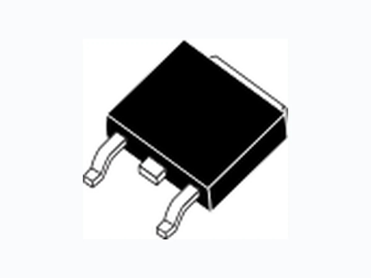
2SJ687 NEC
Document overview
- Manufacturer or author: Provided By digicamel.com
- PDF pages: 8
Technical content
The information in this document is subject to change without notice. Before using this document, please confirm that this is the latest version. Not all products and/or types are available in every country. Please check with an NEC Electronics sales representative for availability and additional information. MOS FIELD EFFECT TRANSISTOR 2SJ687 SWITCHING P-CHANNEL POWER MOSFET DATA SHEET Document No. D18719EJ2V0DS00 (2nd edition) Date Published May 2007 NS Printed in Japan 2007 The mark <R> shows major revised points. The revised points can be easily searched by copying an "<R>" in the PDF file and specifying it in the "Find what:" field.
DESCRIPTION
The 2SJ687 is P-channel MOSFET device and a excellent switch that can be driven by a low power-supply voltage.
FEATURES
- Low on-state resistance R DS(on)1 = 7.0 mΩ MAX. (VGS = −4.5 V, ID = −10 A) R DS(on)2 = 9.0 mΩ MAX. (VGS = −3.0 V, ID = −10 A) RDS(on)3 = 20 mΩ MAX. (VGS = −2.5 V, ID = −10 A)
- 2.5 V drive available
- Avalanche capability ratings
ORDERING INFORMATION
PART NUMBER LEAD PLATING PACKING PACKAGE 2SJ687-ZK-E1-AY Note 2SJ687-ZK-E2-AY Note Pure Sn (Tin) Tape 2500 p/reel TO-252 (MP-3ZK) 0.27 g TYP. Note Pb-free (This product does not contain Pb in external electrode.) ABSOLUTE MAXIMUM RATINGS (TA = 25°C) Drain to Source Voltage (VGS = 0 V) V DSS −20 V Gate to Source Voltage (VDS = 0 V) V GSS m12 V Drain Current (DC) (TC = 25°C) I D(DC) m20 A Drain Current (pulse) Note1 ID(pulse) m60 A Total Power Dissipation (TC = 25°C) PT1 36 W Total Power Dissipation (TA = 25°C) PT2 1.0 W Channel Temperature T ch 150 °C Storage Temperature T stg −55 to +150 °C Single Avalanche Current Note2 IAS −20 A Single Avalanche Energy Note2 EAS 40 mJ Notes 1. PW ≤ 10 μs, Duty Cycle ≤ 1% 2. Starting Tch = 25°C, VDD = −10 V, RG = 25 Ω, VGS = −12 → 0 V (TO-252)
Data Sheet D18719EJ2V0DS 2 2SJ687 ELECTRICAL CHARACTERISTICS (TA = 25°C) CHARACTERISTICS SYMBOL TEST CONDITIONS MIN. TYP. MAX. UNIT Zero Gate Voltage Drain Current I DSS V DS = −20 V, VGS = 0 V −10 μA Gate Leakage Current I GSS V GS = m12 V, VDS = 0 V m100 nA Gate to Source Cut-off Voltage V GS(off) V DS = −10 V, ID = −1 mA −0.6 −1.2 −1.45 V Forward Transfer Admittance Note | yfs | V DS = −10 V, ID = −10 A 20 S Drain to Source On-state Resistance Note RDS(on)1 V GS = −4.5 V, ID = −10 A 5.4 7.0 m Ω R DS(on)2 V GS = −3.0 V, ID = −10 A 7.1 9.0 m Ω R DS(on)3 V GS = −2.5 V, ID = −10 A 10.8 20 m Ω Input Capacitance C iss V DS = −10 V, 4400 pF Output Capacitance C oss V GS = 0 V, 1070 pF Reverse Transfer Capacitance C rss f = 1 MHz 760 pF Turn-on Delay Time t d(on) V DD = −10 V, ID = −10 A, 36 ns Rise Time t r V GS = −4.5 V, 220 ns Turn-off Delay Time t d(off) R G = 3 Ω 270 ns Fall Time t f 310 ns Total Gate Charge Q G V DD = −16 V, 57 nC Gate to Source Charge Q GS V GS = −4.5 V, 12 nC Gate to Drain Charge Q GD I D = −20 A 28 nC Body Diode Forward Voltage Note VF(S-D) I F = −20 A, VGS = 0 V 0.85 1.5 V Reverse Recovery Time t rr I F = −20 A, VGS = 0 V, 200 ns Reverse Recovery Charge Q rr di/dt = −100 A/μs 240 nC Note Pulsed TEST CIRCUIT 1 AVALANCHE CAPABILITY RG = 25 Ω 50 Ω L VDD VGS = −12 → 0 V BVDSSIAS ID VDS Starting Tch VDD D.U.T. TEST CIRCUIT 3 GATE CHARGE TEST CIRCUIT 2 SWITCHING TIME PG. RG VGS(−) D.U.T. RL VDD τ = 1 sμ Duty Cycle ≤ 1% VGS Wave Form VDS Wave Form VGS(−) 10% 90%VGS 10%0 VDS(−) 90%90% td(on) tr td(off) t f 10% τ VDS ton toff PG. PG. 50 Ω D.U.T. RL VDD IG = −2 mA <R> <R>
Data Sheet D18719EJ2V0DS 3 2SJ687 TYPICAL CHARACTERISTICS (TA = 25°C) DERATING FACTOR OF FORWARD BIAS SAFE OPERATING AREA TOTAL POWER DISSIPATION vs. CASE TEMPERATURE dT - Percentage of Rated Power - % 100 120 0 25 50 75 100 125 150 Tch - Channel Temperature - °C PT - Total Power Dissipation - W 0 25 50 75 100 125 150 TC - Case Temperature - °C FORWARD BIAS SAFE OPERATING AREA ID - Drain Current - A -0.1 -10 -100 -1000 -0.1 -1 -10 -100 PW = 1 ms 10 ms ID(pulse) ID(DC) RDS(on) Limited (VGS = −4.5 V) TC = 25°C Single Pulse Power Dissipation Limited VDS - Drain to Source Voltage - V TRANSIENT THERMAL RESISTANCE vs. PULSE WIDTH rth(t) - Transient Thermal Resistance - °C/W 0.01 0.1 100 1000 Rth(ch-A) = 125°C/Wi Rth(ch-C) = 3.47°C/Wi Single Pulse PW - Pulse Width - s 100 μ 1 m 10 m 100 m 1 10 100 1000
Data Sheet D18719EJ2V0DS 4 2SJ687 DRAIN CURRENT vs. DRAIN TO SOURCE VOLTAGE FORWARD TRANSFER CHARACTERISTICS ID - Drain Current - A -20 -40 -60 0- 1 - 2 - 3 VGS = −4.5 V −2.5 V Pulsed VDS - Drain to Source Voltage - V ID - Drain Current - A -0.0001 -0.001 -0.01 -0.1 -10 -100 0 - 1- 2- 3 VDS = −10 V Pulsed Tch = −55°C −25°C 25°C 75°C 125°C 150°C V GS - Gate to Source Voltage - V GATE TO SOURCE CUT-OFF VOLTAGE vs. CHANNEL TEMPERATURE FORWARD TRANSFER ADMITTANCE vs. DRAIN CURRENT VGS(off) – Gate to Source Cut-off Voltage - V -0.5 -1.5 -75 -25 25 75 125 175 VDS = −10 V ID = −1 mA Tch - Channel Temperature - °C | yfs | - Forward Transfer Admittance - S 0.01 0.1 100 VDS = −10 V Pulsed Tch = −55°C −25°C 25°C 75°C 125°C 150°C ID - Drain Current - A DRAIN TO SOURCE ON-STATE RESISTANCE vs. DRAIN CURRENT DRAIN TO SOURCE ON-STATE RESISTANCE vs. GATE TO SOURCE VOLTAGE RDS(on) - Drain to Source On-state Resistance - mΩ 0- 5 - 1 0 - 1 5 ID = −10 A Pulsed VGS - Gate to Source Voltage - V RDS(on) - Drain to Source On-state Resistance - mΩ -0.1 -1 -10 -100 VGS = −2.5 V −4.5 V Pulsed ID - Drain Current - A <R>
Data Sheet D18719EJ2V0DS 5 2SJ687 DRAIN TO SOURCE ON-STATE RESISTANCE vs. CHANNEL TEMPERATURE CAPACITANCE vs. DRAIN TO SOURCE VOLTAGE RDS(on) - Drain to Source On-state Resistance - mΩ -75 -25 25 75 125 175 ID = −10 A Pulsed VGS = −2.5 V −4.5 V Tch - Channel Temperature - °C Ciss, Coss, Crss - Capacitance - pF 100 1000 10000 VGS = 0 V f = 1 MHz Crss Ciss Coss VDS - Drain to Source Voltage - V SWITCHING CHARACTERISTICS DYNAMIC INPUT/OUTPUT CHARACTERISTICS td(on), tr, td(off), tf - Switching Time - ns 100 1000 -0.1 -1 -10 -100 VDD = −10 V VGS = −4.5 V RG = 3 Ω td(on) tr td(off) tf ID - Drain Current - A VDS - Drain to Source Voltage - V -10 -15 -20 -25 0 1 02 03 04 05 06 0 VDS VGS ID = −20 A VDD = −16 V −10 V −4 V Q G - Gate Charge - nC VGS - Gate to Source Voltage - V SOURCE TO DRAIN DIODE FORWARD VOLTAGE REVERSE RECOVERY TIME vs. DIODE FORWARD CURRENT IF - Diode Forward Current - A -0.01 -0.1 -10 -100 -1.5-1-0.50 Pulsed −4.5 V −2.5 V VGS = 0 V VF(S-D) - Source to Drain Voltage - V trr - Reverse Recovery Time - ns 100 1000 10000 -0.1 -1 -10 -100 di/dt = −100 A/μs VGS = 0 V IF - Diode Forward Current - A
Data Sheet D18719EJ2V0DS 6 2SJ687 SINGLE AVALANCHE CURRENT vs. INDUCTIVE LOAD SINGLE AVALANCHE ENERGY DERATING FACTOR IAS - Single Avalanche Current - A -10 -100 0.01 0.1 1 10 Starting Tch = 25°C VDD = −10 V RG = 25 Ω VGS = −12 → 0 V IAS = −20 A EAS = 40 mJ L - Inductive Load - mH Energy Derating Factor - % 0 100 120 25 50 75 100 125 150 VDD = −10 V RG = 25 Ω VGS = −12 → 0 V IAS ≤ −20 A Starting Tch - Starting Channel Temperature - °C
Data Sheet D18719EJ2V0DS 7 2SJ687 PACKAGE DRAWING (Unit: mm) TO-252 (MP-3ZK) 6.5±0.2 2.3±0.1 0.5±0.1 0.76±0.12 0 to 0.25 0.5±0.1 1.0 No Plating No Plating 5.1 TYP. 1.0 TYP.6.1±0.2 0.51 MIN. 4.0 MIN.0.8 10.4 MAX. (9.8 TYP.) 4.3 MIN. 1.14 MAX. 2.3 2.3 1. Gate 2. Drain 3. Source 4. Fin (Drain) EQUIVALENT CIRCUIT Source Body DiodeGate Drain Remark Strong electric field, when exposed to this device , can cause destruction of the gate oxide and ultimately degrade the device operation. Steps must be taken to stop generation of static electricity as much as possible, and quickly dissipate it once, when it has occurred.
The information in this document is current as of May, 2007. The information is subject to change without notice. For actual design-in, refer to the latest publications of NEC Electronics data sheets or data books, etc., for the most up-to-date specifications of NEC Electronics products. Not all products and/or types are available in every country. Please check with an NEC Electronics sales representative for availability and additional information. No part of this document may be copied or reproduced in any form or by any means without the prior written consent of NEC Electronics. NEC Electronics assumes no responsibility for any errors that may appear in this document. NEC Electronics does not assume any liability for infringement of patents, copyrights or other intellectual property rights of third parties by or arising from the use of NEC Electronics products listed in this document or any other liability arising from the use of such products. No license, express, implied or otherwise, is granted under any patents, copyrights or other intellectual property rights of NEC Electronics or others. Descriptions of circuits, software and other related information in this document are provided for illustrative purposes in semiconductor product operation and application examples. The incorporation of these circuits, software and information in the design of a customer's equipment shall be done under the full responsibility of the customer. NEC Electronics assumes no responsibility for any losses incurred by customers or third parties arising from the use of these circuits, software and information. While NEC Electronics endeavors to enhance the quality, reliability and safety of NEC Electronics products, customers agree and acknowledge that the possibility of defects thereof cannot be eliminated entirely. To minimize risks of damage to property or injury (including death) to persons arising from defects in NEC Electronics products, customers must incorporate sufficient safety measures in their design, such as redundancy, fire-containment and anti-failure features. NEC Electronics products are classified into the following three quality grades: "Standard", "Special" and "Specific". The "Specific" quality grade applies only to NEC Electronics products developed based on a customer- designated "quality assurance program" for a specific application. The recommended applications of an NEC Electronics product depend on its quality grade, as indicated below. Customers must check the quality grade of each NEC Electronics product before using it in a particular application. The quality grade of NEC Electronics products is "Standard" unless otherwise expressly specified in NEC Electronics data sheets or data books, etc. If customers wish to use NEC Electronics products in applications not intended by NEC Electronics, they must contact an NEC Electronics sales representative in advance to determine NEC Electronics' willingness to support a given application. (Note) M8E 02. 11-1 (1) (2) "NEC Electronics" as used in this statement means NEC Electronics Corporation and also includes its majority-owned subsidiaries. "NEC Electronics products" means any product developed or manufactured by or for NEC Electronics (as defined above). Computers, office equipment, communications equipment, test and measurement equipment, audio and visual equipment, home electronic appliances, machine tools, personal electronic equipment and industrial robots. Transportation equipment (automobiles, trains, ships, etc.), traffic control systems, anti-disaster systems, anti-crime systems, safety equipment and medical equipment (not specifically designed for life support). Aircraft, aerospace equipment, submersible repeaters, nuclear reactor control systems, life support systems and medical equipment for life support, etc. "Standard": "Special": "Specific":