


 Download PDF
2R-8-U YAGEO
Document overview
- PDF pages: 5
Technical content
Page 1
Page 2

Gas Discharge Tube (GDT) Data Sheet
Features
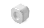
■ Provide ultra-fast response to surge voltage from slow-rising surge of100V/s to rapid-rising surge of 1KV/μs ■ Stable breakdown voltage ■ High insulation resistance ■ Low capacitance (≤1.5pF) ■ High holdover voltage ■ Large absorbing transient current capability ■ Micro-Gap Design ■ Size: 8.0mm\*6.0mm ■ Storage and operating temperature: -40℃ ~ +85℃ ■ Meets MSL level 1, per J-STD-020 ■ Safety certification: UL
Applications
■ Repeaters, Modems ■ Telephone Interface, Line cards ■ Data communication equipment ■ Line test equipment
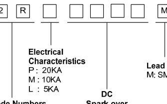
Part Number Code
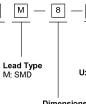
Dimensions
| M Type | Symbol | Dimension (mm) | |
| Spec. | Tolerance | ||
| D | 8.0 | ±0.2 | |
| D1 | 8.0 | ±0.2 | |
| T | 6.0 | ±0.2 | |
| B | 0.5 | ±0.2 | |
Page 3

Electrical Characteristics
| Part Number | DC Spark-over Voltage | Maximum Impulse Spark-over Voltage | Nominal Impulse Discharge Current | Alternating Discharge Current | Impulse Life | Minimum Insulation Resistance | Maximum Capacitance | Device Marking Code | |
|---|---|---|---|---|---|---|---|---|---|
| 100V/s | 1000V/μs | 8/20μs 10times | 50Hz,1sec | 10/1000μs 100A | Test Voltage | (GΩ) | 1MHz | ||
| (V) | (V) | (KA) | (A) | (times) | DC(V) | (pF) | |||
| 2RP075M-8-U | 75±20% | 600 | 20 | 20 | 500 | 25 | 1.0 | 1.5 | None |
| 2RP090M-8-U | 90±20% | 600 | 20 | 20 | 500 | 50 | 1.0 | 1.5 | None |
| 2RP120M-8-U | 120±20% | 600 | 20 | 20 | 500 | 50 | 1.0 | 1.5 | None |
| 2RP150M-8-U | 150±20% | 700 | 20 | 20 | 500 | 100 | 1.0 | 1.5 | None |
| 2RP230M-8-U | 230±20% | 700 | 20 | 20 | 500 | 100 | 1.0 | 1.5 | None |
| 2RP250M-8-U | 250±20% | 800 | 20 | 20 | 500 | 100 | 1.0 | 1.5 | None |
| 2RP300M-8-U | 300±20% | 900 | 20 | 20 | 500 | 100 | 1.0 | 1.5 | None |
| 2RP350M-8-U | 350±20% | 900 | 20 | 20 | 500 | 100 | 1.0 | 1.5 | None |
| 2RP400M-8-U | 400±20% | 1000 | 20 | 20 | 500 | 100 | 1.0 | 1.5 | None |
| 2RP470M-8-U | 470±20% | 1100 | 20 | 20 | 500 | 250 | 1.0 | 1.5 | None |
| 2RP600M-8-U | 600±20% | 1300 | 20 | 20 | 500 | 250 | 1.0 | 1.5 | None |
| 2RP800M-8-U | 800±20% | 1500 | 20 | 20 | 500 | 250 | 1.0 | 1.5 | None |
| 2RM1000M-8-U | 1000±20% | 2200 | 10 | 10 | 300 | 500 | 1.0 | 1.5 | None |
| 2RM1200M-8-U | 1200±20% | 2300 | 10 | 10 | 300 | 500 | 1.0 | 1.5 | None |
| 2RM1400M-8-U | 1400±20% | 2400 | 10 | 10 | 300 | 500 | 1.0 | 1.5 | None |
| 2RM1500M-8-U | 1500±20% | 2400 | 10 | 10 | 300 | 500 | 1.0 | 1.5 | None |
| 2RM1600M-8-U | 1600±20% | 2600 | 10 | 10 | 300 | 500 | 1.0 | 1.5 | None |
| 2RL2000M-8-U | 2000±20% | 3200 | 5 | 5 | 300 | 500 | 1.0 | 1.5 | None |
| 2RL2500M-8-U | 2500±20% | 3600 | 5 | 5 | 300 | 500 | 1.0 | 1.5 | None |
Electrical Ratings
| Items | Test Condition/Description | Requirement |
|---|---|---|
| DC Spark-over Voltage | The voltage is measured with voltage ramp dv/dt=100V/s. | To meet the specified value |
| Maximum Impulse Spark-over Voltage | The maximum impulse spark-over voltage is measured with voltage ramp dv/dt=1000V/μs. | |
| Impulse Discharge Current | Maximum 8/20μs surge current that can be applied between two electrodes, 5 positive and 5 negative surges, with 3 minutes interval time. |
Page 4

| Alternating Discharge Current | Rated RMS value of AC current at 50Hz, 1 sec. for 10 times with interval time 3 min. | |
|---|---|---|
| Insulation Resistance | The resistance of gas tube shall be measured between two electrodes. | |
| Capacitance | The capacitance of gas tube shall be measured between two electrodes. Test frequency: 1MHz |
Recommended Soldering Conditions
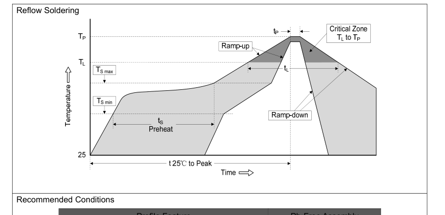
| Profile Feature | Pb-Free Assembly |
| Average ramp-up rate (T to T ) L P | 3℃/second max. |
| Preheat -Temperature Min (T ) S min -Temperature Max (T ) S max -Time (min to max) (ts) | 150℃ 200℃ 60-180 seconds |
| T to T S max L -Ramp-up Rate | 3℃/second max. |
| Time maintained above: -Temperature (T ) L -Time (t ) L | 217℃ 60-150 seconds |
| Peak Temperature (T ) P | 260℃ |
| Time within 5℃ of actual Peak Temperature (t ) P | 20-40 seconds |
| Ramp-down Rate | 6℃/second max. |
| Time 25℃ to Peak Temperature | 8 minutes max. |
Page 5

Packaging
| Tape | Symbol | Dimension (mm) | |
| Spec. | Tolerance | ||
| W | 16.00 | ±0.20 | |
| P0 | 4.00 | ±0.10 | |
| P1 | 12.00 | ±0.20 | |
| P2 | 2.00 | ±0.10 | |
| D0 | 1.55 | ±0.05 | |
| E | 1.75 | ±0.10 | |
| F | 7.50 | ±0.10 | |
| A0 | 6.35 | ±0.10 | |
| K0 | 6.55 | ±0.10 | |
| B0 | 8.65 | ±0.10 | |
| t0 | 0.50 | ±0.10 | |
| Reel | D | 330.00 | ±2.00 |
| d | 13.00 | ±0.50 | |
| L | 20.00 | ±2.00 | |
| t | 2.00 | ±0.20 | |
| Quantity: 600pcs | |||