


 Download PDF
2R-4-H3.5 YAGEO
Document overview
- PDF pages: 6
Technical content
Page 1

Page 2

Gas Discharge Tube (GDT) Data Sheet
Features
■ Provide ultra-fast response to surge voltage from slow-rising
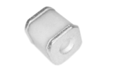
surge of 100V/s to rapid-rising surge of 1KV/μs ■ Stable breakdown voltage ■ High insulation resistance ■ Low capacitance (≤0.5pF) ■ High holdover voltage ■ Large absorbing transient current capability ■ Micro-Gap Design ■ Size: 3.5mm\*4.0mm ■ Storage and operational temperature: -40℃ ~ +85℃ ■ Meets MSL level 1, per J-STD-020 ■ Safety certification: UL
Applications
■ Repeaters, Modems. ■ Telephone Interface, Line cards. ■ Data communication equipment. ■ Line test equipment
Part Number Code
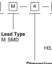
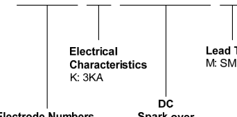
Dimensions
| M Type | Symbol | Dimension (mm) | |
| Spec. | Tolerance | ||
| D | 3.5 | ±0.2 | |
| T | 4.0 | ±0.3 | |
| B | 0.4 | ±0.2 | |
Page 3

Electrical Characteristics
| Part Number | Type ① | DC Spark-over Voltage | Maximum Impulse Spark-over Voltage | Nominal Impulse Discharge Current | Impulse Discharge Voltage | Minimum Insulation Resistance | Maximum Capacitance | Device Marking Code | |
|---|---|---|---|---|---|---|---|---|---|
| 100V/s | 1000V/μs | 8/20μs 10times | 10/700μs 10times | Test Voltage | (GΩ) | 1MHz | |||
| (V) | (V) | (KA) | (KV) | DC(V) | (pF) | ||||
| 2RK090M-4 | H3.5 | 90±30% | 650 | 3 | 6 | 50 | 1 | 0.5 | None |
| 2RK150M-4 | H3.5 | 150±30% | 650 | 3 | 6 | 100 | 1 | 0.5 | None |
| 2RK200M-4 | H3.5 | 200±30% | 750 | 3 | 6 | 100 | 1 | 0.5 | None |
| 2RK250M-4 | H3.5 | 250±30% | 750 | 3 | 6 | 100 | 1 | 0.5 | None |
| 2RK300M-4 | H3.5 | 300±30% | 850 | 3 | 6 | 100 | 1 | 0.5 | None |
| 2RK350M-4 | H3.5 | 350±30% | 850 | 3 | 6 | 100 | 1 | 0.5 | None |
| 2RK400M-4 | H3.5 | 400±30% | 900 | 3 | 6 | 100 | 1 | 0.5 | None |
| 2RK470M-4 | H3.5 | 470±30% | 1000 | 3 | 6 | 250 | 1 | 0.5 | None |
Notes:① Specific code by request.
Electrical Ratings
| Items | Test Condition/Description | Requirement |
|---|---|---|
| DC Spark-over Voltage | The voltage is measured with voltage ramp dv/dt=100V/s. | To meet the specified value |
| Maximum Impulse Spark-over Voltage | The maximum impulse spark-over voltage is measured with voltage ramp dv/dt=1000V/μs. | |
| Impulse Discharge Current | Maximum 8/20μs surge current that can be applied between two electrodes, 5 positive and 5 negative surges, with 3 minutes interval time. | |
| Insulation Resistance | The resistance of gas tube shall be measured between two electrodes. | |
| Capacitance | The capacitance of gas tube shall be measured between two electrodes. Test frequency: 1MHz |
Page 4

Recommended Soldering Conditions
Reflow Soldering


| Profile Feature | Pb-Free Assembly |
| Average ramp-up rate (T to T P) L | 3℃/second max. |
| Preheat -Temperature Min (T ) S min -Temperature Max (T ) S max -Time (min to max) (ts) | 150℃ 200℃ 60-180 seconds |
| T to T S max L -Ramp-up Rate | 3℃/second max. |
| Time maintained above: -Temperature (T ) L -Time (t ) L | 217℃ 60-150 seconds |
| Peak Temperature (T ) P | 260℃ |
| Time within 5℃of actual Peak Temperature (t ) P | 20-40 seconds |
| Ramp-down Rate | 6℃/second max. |
| Time 25℃to Peak Temperature | 8 minutes max. |
Page 5

Packaging
| Tape | Symbol | Dimension (mm) | |
| Spec. | Tolerance | ||
| W | 16.00 | ±0.20 | |
| P | 8.00 | ±0.10 | |
| P0 | 4.00 | ±0.10 | |
| P1 | 2.00 | ±0.10 | |
| D | 1.50 | +0.10/-0 | |
| E | 1.75 | ±0.10 | |
| F | 7.50 | ±0.10 | |
| A0 | 3.80 | ±0.10 | |
| B0 | 4.30 | ±0.10 | |
| K0 | 3.80 | ±0.10 | |
| t | 0.30 | ±0.10 | |
| Reel | D | 330.00 | ±2.00 |
| d | 13.00 | ±0.50 | |
| L | 16.00 | ±2.00 | |
| t | 2.00 | ±0.20 | |
| Quantity: 2000pcs | |||
Page 6
Product specification
Circuit Protection Components
LEGAL DISCLAIMER
YAGEO, its distributors and agents (collectively, “YAGEO”), hereby disclaims any and all liabilities for any errors, inaccuracies or incompleteness contained in any product related information, including but not limited to product specifications, datasheets, pictures and/or graphics. YAGEO may make changes, modifications and/or improvements to product related information at any time and without notice.
YAGEO makes no representation, warranty, and/or guarantee about the fitness of its products for any particular purpose or the continuing production of any of its products. To the maximum exten t permitted by law, YAGEO disclaims (i) any and all liability arising out of the application or use of any YAGEO product, (ii) any and all liability, including without limitation special, consequential or incidental damages, and (iii) any and all implied warranties, including warranties of fitness for a particular purpose, non -infringement and merchantability.
YAGEO products are designed for general purpose applications under normal operation and usage conditions. Please contact YAGEO for the applications listed below which require especially high reliability for the prevention of defects which might directly cause damage to the third party's life, body or property: Aerospace equipment (artificial satellite, rocket, etc.), Atomic energy-related equipment, Aviation equipment, Disaster prevention equipment, crime prevention equipment, Electric heating apparatus, burning equipment, Highly public information network equipment, data-processing equipment , Medical devices, Military equipment, Power generation control equipment, Safety equipment, Traffic signal equipment, Transportation equipment and
Undersea equipment, or for any other application or use in which the failure of YAGEO products could result in personal injury or death, or serious property damage. Particularly YAGEO Corporation and its affiliates do not recommend the use of commercial or automotive grade products for high reliability applications or manned space flight.
Information provided here is intended to indicate product specifications only. YAGEO reserves all the rights for revising this content without further notification, as long as products are unchanged. Any product change will be announced by PCN.
www.yageo.com