
 Download PDF
PIQ AITSEMI
Document overview
- PDF pages: 4
Technical content
Page 1
- FEATURE 1. Excellent solder heat resistance(add “C” is for high current type) 2. Low voltage drops and small variations inductance
- APPLICATION 1. DC power supply circuits 2. Power line choke coils…etc
- ORDERING INFORMATION
PIQ322516
-R12
T
PN
Inductance
K: ±10% M:±20%
- SHAPE AND DIMENSION ●SCHEMATICS AND LAND PATTERNS(mm)
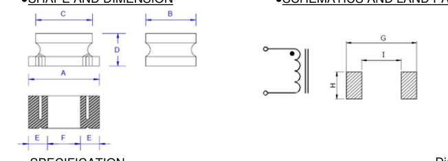
- SPECIFICATION Dimension in mm
| TYPE | A | B | C | D | E | F | G | I | H |
|---|---|---|---|---|---|---|---|---|---|
| PIQ201610T[0806] | 2.0±0.30 | 1.6±0.30 | 1.0 MAX | 2.10 | 0.70 | 2.00 | |||
| PIQ252010H[1008] | 2.5±0.20 | 2.0±0.35 | 1.0 MAX | 0.85 | 0.8 | 2.70 | 0.80 | 2.20 | |
| PIQ252012H[1008] | 2.5±0.30 | 2.0±0.30 | 1.2 MAX | 0.85 | 0.8 | 2.70 | 0.80 | 2.20 | |
| PIQ322516[1210] | 3.2±0.30 | 2.5±0.30 | 2.5±0.30 | 1.6±0.30 | 0.9 | 1.3 | 3.70 | 1.10 | 2.90 |
| PIQ321618[1206] | 3.2±0.30 | 1.6±0.30 | 2.3±0.30 | 1.8±0.30 | 0.9 | 1.3 | 3.70 | 0.70 | 2.00 |
| PIQ322520[1210] | 3.2±0.30 | 2.5±0.30 | 2.5±0.30 | 2.0±0.30 | 0.9 | 1.3 | 3.70 | 1.10 | 2.90 |
| PIQ453226[1812] | 4.5±0.30 | 3.2±0.30 | 3.6±0.30 | 2.6±0.30 | 1.0 | 1.0 | 5.00 | 1.00 | 3.70 |
| PIQ575047[2220] | 5.7±0.30 | 5.0±0.30 | 5.0±0.30 | 4.7±0.30 | 1.3 | 1.7 | 6.20 | 1.70 | 5.50 |
| PIQ322520C[1210] | 3.2±0.30 | 2.5±0.30 | 2.5±0.30 | 2.0±0.30 | 0.9 | 1.3 | 3.70 | 1.10 | 2.90 |
| PIQ453226C[1812] | 4.5±0.30 | 3.2±0.30 | 3.6±0.30 | 2.6±0.30 | 1.0 | 1.0 | 5.00 | 1.00 | 3.70 |
Note1. Measurement frequency of Inductance value : at 1kHz, 0.25V Note2. Measurement ambient temperature of L, DCR and IDC : at 25°C Note3. IDC : This indicates the value of current when the inductances is 10% lower than its initial value at D.C. superimposition or D.C. current when at ∆t=40℃,which is lower.(Ta=20°C) Note4. Inductance tolerance: K: ±10% ; M: ±20% Note5. This specification might be changed without notice due to under developing and improving.
Page 2
- ELECTRICAL CHARACTERISTICS
| PART NUMBER | Inductance (uH) | D.C.R.(ΩMax)/Rated D.C. Current(A) | ||||
|---|---|---|---|---|---|---|
| PIQ201610T | PIQ252010H | PIQ252012H | PIQ322516 | PIQ321618 | ||
| R12 | 0.12 | 0.13 / 0.184 | ||||
| R27 | 0.27 | |||||
| R47 | 0.47 | 0.17 / 0.178 | ||||
| 1R0 | 1.0 | 0.065 / 3.00 | 0.06 / 1.48 | 0.49 / 0.175 | ||
| 1R5 | 1.5 | 0.52 / 0.155 | ||||
| 2R2 | 2.2 | 0.12 / 1.90 | 0.125 / 1.25 | 0.54 / 0.140 | ||
| 3R3 | 3.3 | 0.160 / 1.08 | 0.61 / 0.130 | |||
| 4R2 | 4.2 | |||||
| 4R7 | 4.7 | 0.40 / 0.90 | 0.236 / 0.98 | 1.70 / 0.120 | ||
| 6R8 | 6.8 | 0.371 / 0.79 | 2.00 / 0.110 | |||
| 8R2 | 8.2 | 0.471 / 0.72 | 2.20 / 0.105 | |||
| 100 | 10 | 0.56 / 0.60 | 0.576 / 0.66 | 2.50 / 0.100 | ||
| 120 | 12 | 0.684 / 0.59 | 2.70 / 0.095 | |||
| 150 | 15 | 0.888 / 0.54 | 2.90 / 0.090 | |||
| 180 | 18 | 1.087 / 0.48 | 3.00 / 0.085 | |||
| 220 | 22 | 1.343 / 0.43 | 3.10 / 0.085 | |||
| 330 | 33 | 2.245 / 0.35 | 3.80 / 0.080 | |||
| 390 | 39 | 4.50 / 0.085 | ||||
| 470 | 47 | 3.064 / 0.29 | 6.30 / 0.085 | |||
| 560 | 56 | 4.120 / 0.27 | 7.10 / 0.050 | |||
| 680 | 68 | 5.289 / 0.24 | 7.90 / 0.050 | |||
| 820 | 82 | 7.223 / 0.20 | 8.70 / 0.045 | |||
| 101 | 100 | 8.209 / 0.19 | 11.57 / 0.045 | |||
| 151 | 150 | 12.57 / 0.16 | 15.03 / 0.015 | |||
| 181 | 180 | 19.65 / 0.14 | 16.60 / 0.013 | |||
| 221 | 220 | 22.31 / 0.13 | ||||
| 271 | 270 | 24.61 / 0.12 | 29.70 / 0.011 | |||
| 331 | 330 | 28.21 / 0.11 | 43.06 / 0.010 | |||
| 391 | 390 | 32.19 / 0.10 | ||||
| 471 | 470 | 48.75 / 0.09 | 53.50 / 0.008 | |||
| 561 | 560 | 53.89 / 0.08 | ||||
| 681 | 680 | 63.01 / 0.07 | ||||
| 821 | 820 | 66.10 / 0.005 | ||||
| 102 | 1000 | |||||
PIQ201610T/ PIQ252010H/ PIQ252012H: Measurement frequency of Inductance value : at 1MHz, 1V/ 0.25V/ 0.1V
Page 3
| PART NUMBER | Inductance (uH) | D.C.R.(ΩMax)/Rated D.C. Current(A) | ||||
|---|---|---|---|---|---|---|
| PIQ322520 | PIQ453226 | PIQ575047 | PIQ322520C | PIQ453226C | ||
| R12 | 0.12 | 0.010 / 6.00 | ||||
| R27 | 0.27 | 0.25 / 0.600 | 0.014 / 5.30 | |||
| R47 | 0.47 | 0.018 / 4.80 | ||||
| 1R0 | 1.0 | 0.50 / 0.445 | 0.20 / 0.500 | 0.027 / 4.00 | 0.117 / 0.800 | 0.08 / 1.08 |
| 1R5 | 1.5 | 0.60 / 0.400 | 0.30 / 0.500 | 0.031 / 3.70 | 0.09 / 1.00 | |
| 2R2 | 2.2 | 0.80 / 0.370 | 0.30 / 0.500 | 0.041 / 3.20 | 0.169 / 0.600 | 0.11 / 0.90 |
| 3R3 | 3.3 | 1.00 / 0.300 | 0.35 / 0.500 | 0.050 / 2.90 | 0.180 / 0.500 | 0.13 / 0.80 |
| 4R2 | 4.2 | |||||
| 4R7 | 4.7 | 1.20 / 0.270 | 0.40 / 0.500 | 0.057 / 2.70 | 0.260 / 0.450 | 0.15 / 0.75 |
| 6R8 | 6.8 | 1.50 / 0.240 | 0.50 / 0.450 | 0.100 / 2.00 | 0.300 / 0.430 | 0.20 / 0.72 |
| 8R2 | 8.2 | 1.60 / 0.225 | 0.56 / 0.450 | 0.392 / 0.400 | ||
| 100 | 10 | 1.80 / 0.190 | 0.56 / 0.400 | 0.130 / 1.70 | 0.572 / 0.300 | 0.24 / 0.65 |
| 120 | 12 | 2.00 / 0.180 | 0.62 / 0.380 | 0.200 / 1.50 | 0.650 / 0.290 | |
| 150 | 15 | 2.20 / 0.170 | 0.73 / 0.360 | 0.210 / 1.40 | 0.700 / 0.285 | 0.32 / 0.57 |
| 180 | 18 | 2.50 / 0.160 | 0.82 / 0.340 | 0.800 / 0.265 | ||
| 220 | 22 | 2.80 / 0.150 | 0.94 / 0.320 | 0.270 / 1.20 | 0.923 / 0.250 | 0.60 / 0.42 |
| 330 | 33 | 3.50 / 0.115 | 1.20 / 0.270 | 0.450 / 0.90 | 1.352 / 0.230 | 1.00 / 0.31 |
| 390 | 39 | 3.90 / 0.110 | 1.40 / 0.240 | |||
| 470 | 47 | 4.30 / 0.100 | 1.50 / 0.220 | 0.560 / 0.80 | 1.690 / 0.170 | 1.10 / 0.28 |
| 560 | 56 | 4.90 / 0.085 | 1.70 / 0.200 | 2.00 / 0.160 | 1.34 / 0.26 | |
| 680 | 68 | 5.50 / 0.080 | 1.90 / 0.180 | 0.940 / 0.64 | 2.67 / 0.150 | 1.70 / 0.22 |
| 820 | 82 | 6.20 / 0.080 | 2.20 / 0.170 | |||
| 101 | 100 | 7.00 / 0.080 | 2.50 / 0.160 | 1.20 / 0.56 | 4.55 / 0.100 | 2.20 / 0.19 |
| 151 | 150 | 9.30 / 0.070 | 2.66 / 0.42 | 5.80 / 0.095 | 3.50 / 0.13 | |
| 181 | 180 | 10.20 / 0.065 | 4.50 / 0.120 | 6.27 / 0.090 | ||
| 221 | 220 | 11.80 / 0.065 | 5.40 / 0.110 | 3.36 / 0.32 | 10.90 / 0.070 | 4.00 / 0.11 |
| 271 | 270 | 12.50 / 0.065 | 6.80 / 0.100 | |||
| 331 | 330 | 13.00 / 0.065 | 8.20 / 0.095 | 6.16 / 0.27 | 13.00 / 0.060 | 6.80 / 0.10 |
| 391 | 390 | 22.00 / 0.050 | 9.70 / 0.090 | 22.10 / 0.060 | ||
| 471 | 470 | 25.00 / 0.045 | 11.80 / 0.080 | 7.56 / 0.24 | 24.70 / 0.060 | |
| 561 | 560 | 28.00 / 0.040 | 14.50 / 0.070 | 28.60 / 0.060 | ||
| 681 | 680 | 30.00 / 0.035 | 17.00 / 0.065 | 11.30 / 0.19 | ||
| 821 | 820 | 20.50 / 0.060 | ||||
| 102 | 1000 | 39.20 / 0.030 | 25.00 / 0.050 | 14.40 / 0.15 | ||
Page 4
- GENERAL CHARACTERISTICS
- Operating temperature range: -40 TO + 85°C (Includes temperature when the coil is heated) 2. External appearance: On visual inspection, the coil has external defects.
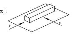
- Terminal strength: After soldering. Between copper plate and terminals of coil. Push in two directions of X.Y withstanding at below conditions. Terminal should not peel off. (refer to figure at right) 0.5kg 4. Insulating resistance: Over 100MΩ at 100V D.C. between coil and core. 5. Dielectric strength: No dielectric breakdown at 100V D.C. for 1 minute between coil and core. 6. Temperature characteristics: Inductance coefficient (0~2,000)x10-6/°C (-25~+80°C). 7. Humidity characteristics(Moisture Resistance): Inductance deviation within ±5%, after 96 hours in 90~95% relative humidity at 40 ±2°C and 1 hour drying under normal condition. 8. Vibration resistance: Inductance deviation within ±5%, after vibration for 1 hour. In each of three
orientations at sweep vibration (10~55~10 Hz) with 1.5mm P-P amplitudes. 9. Shock resistance: Inductance deviation within ±5%, after being dropped once with 981m/s2 (100G) shock attitude upon a rubber block method shock testing machine, in three different orientations. 10. Resistance to Soldering Heat: 260°C, 10 seconds. 11. Storage environment Storage condition: Temperature Range: 10°C ~ 35°C (Generally: 21°C ~ 31°C) Humidity Range: 50% ~ 80% RH (Generally: 65% ~ 75%) Transportation condition: Temperature Range: -35°C ~ 85°C, Humidity Range: 50% ~ 95% RH 12. Use components within 6 months. If 6 months or more have elapsed, check soldarability before use.
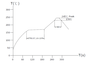
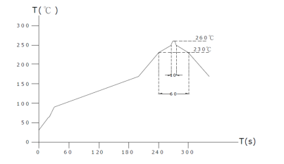
- Reflow profile recommend:
Lead - free heat endurance test
Lead-free the recommended reflow condition