

 Download PDF
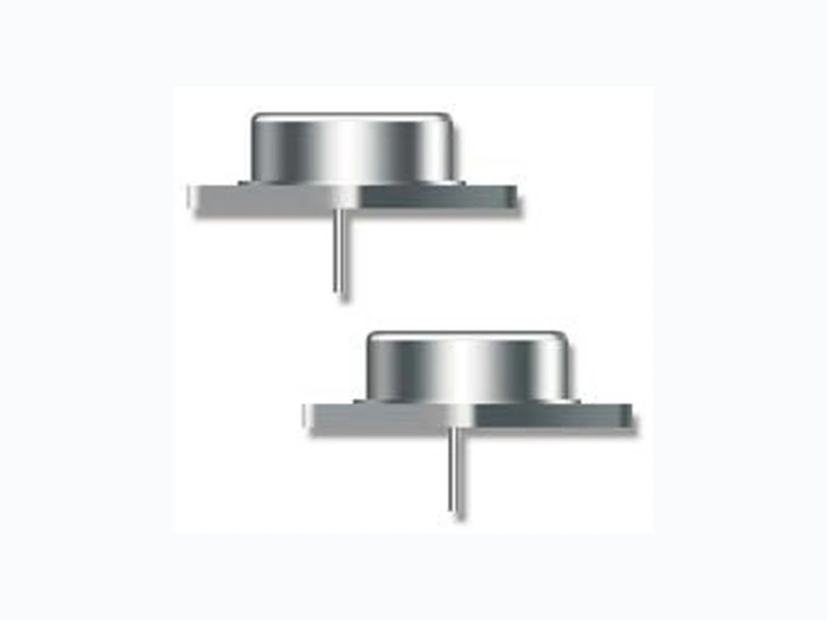
2N6676 MA-COM
Document overview
- Manufacturer or author: Provided By digicamel.com
- PDF pages: 4
Technical content
Features
Available in JAN, JANTX, JANTXV per MIL-PRF-19500/538 TO-3 (TO-204AA) Package
Electrical Characteristics
Parameter Test Conditions Symbol Units Min. Max. Off Characteristics Collector - Emitter Breakdown Voltage IC = 200 mAdc, 2N6676 IC = 200 mAdc, 2N6678 V(BR)CEO Vdc 300 400 — Collector - Emitter Cutoff Current VCE = 450 Vdc, VBE = -1.5 Vdc, 2N6676 VCE = 650 Vdc, VBE = -1.5 Vdc, 2N6678 ICEX µAdc — 1.0 Emitter - Base Cutoff Current VEB = 7 Vdc IEBO mAdc — 2.0 Collector - Base Cutoff Current VCB = 450 Vdc, 2N6676 VCB = 650 Vdc, 2N6678 ICBO mAdc — 1.0 On Characteristics1 Forward Current Transfer Ratio IC = 1 Adc, VCE = 3 Vdc IC = 15 Adc, VCE = 3 Vdc HFE - 15 Collector - Emitter Sustaining Voltage IC = 15 Adc, IB = 3 Adc VCE(SAT) Vdc — 1.0 Base - Emitter Saturation Voltage IC = 15 Adc, IB = 3 Adc VBE(SAT) Vdc — 1.5 Dynamic Characteristics Small-Signal Short-Circuit Forward Current Transfer Ratio IC = 1 Adc, VCE = 10 Vdc, f = 5 kHz | HFE | - 3 10 Output Capacitance VCB = 10 Vdc, IE = 0, 100 kHz ≤ f ≤ 1 MHz COBO pF 150 500 1. Pulse Test: Pulse Width = 300 μs, Duty Cycle ≤2.0%.
NPN High Power Silicon Transistor Rev. V1 2N6676 & 2N6678 2 2 MACOM Technology Solutions Inc. (MACOM) and its affiliates reserve the right to make changes to the product(s) or information contained herein without notice. Visit www.macom.com for additional data sheets and product information. For further information and support please visit: https://www.macom.com/support DC-0013439 Absolute Maximum Ratings 2. Derate linearly @ 34.2 mW / °C for TA >25°C. Ratings Symbol 2N6676 2N6678 Units Collector - Emitter Voltage VCEO 300 400 Vdc Collector - Base Voltage VCBO/VCBX 450 650 Vdc Emitter - Base Voltage VEBO 8 Vdc Collector Current IC 15 Adc Base Current IB 5 Adc Total Power Dissipation @ TA = +25°C2 @ TA = +25°C PT W 175 Operating & Storage Temperature Range TOP, TSTG -65 to +200 °C Thermal Characteristics Characteristics Symbol Max. Value Thermal Resistance, Junction to Case RθJC 1°C/W Parameter Test Conditions Symbol Units Min. Max. Switching Characteristics Delay Time Rise Time Storage Time Fall Time Cross-Over Time See figure 12 of MIL-PRF-19500/538 TD TR TS TF TC µs — 0.1 0.6 2.5 0.5 0.5 Safe Operating Area DC Tests: TC = +25°C, I Cycle, t = 1.0 s (see figure 4 of MIL-PRF-19500/537) Test 1: VCE = 11.7 Vdc, IC = 15 Adc Test 2: VCE = 30 Vdc, IC = 5.9 Adc Test 3: VCE = 100 Vdc, IC = 0.25 Adc Test 4: VCE = 300 Vdc, IC = 20 mAdc, (for 2N6676) Test 5: VCE = 400 Vdc, IC = 10 mAdc, (for 2N6678) Clamped Switch: TA = +25°C, VCC = 15 Vdc Clamp Voltage = 350; IC = 15 Adc, (2N6676) Clamp Voltage = 450; IC = 15 Adc, (2N6678)
NPN High Power Silicon Transistor Rev. V1 2N6676 & 2N6678 3 3 MACOM Technology Solutions Inc. (MACOM) and its affiliates reserve the right to make changes to the product(s) or information contained herein without notice. Visit www.macom.com for additional data sheets and product information. For further information and support please visit: https://www.macom.com/support DC-0013439 Outline Drawing
NPN High Power Silicon Transistor Rev. V1 2N6676 & 2N6678 4 4 MACOM Technology Solutions Inc. (MACOM) and its affiliates reserve the right to make changes to the product(s) or information contained herein without notice. Visit www.macom.com for additional data sheets and product information. For further information and support please visit: https://www.macom.com/support DC-0013439 MACOM Technology Solutions Inc. All rights reserved. Information in this document is provided in connection with MACOM Technology Solutions Inc ("MACOM") products. These materials are provided by MACOM as a service to its customers and may be used for informational purposes only. Except as provided in MACOM's Terms and Conditions of Sale for such products or in any separate agreement related to this document, MACOM assumes no liability whatsoever. MACOM assumes no responsibility for errors or omissions in these materials. MACOM may make changes to specifications and product descriptions at any time, without notice. MACOM makes no commitment to update the information and shall have no responsibility whatsoever for conflicts or incompatibilities arising from future changes to its specifications and product descriptions. No license, express or implied, by estoppels or otherwise, to any intellectual property rights is granted by this document. THESE MATERIALS ARE PROVIDED "AS IS" WITHOUT WARRANTY OF ANY KIND, EITHER EXPRESS OR IMPLIED, RELATING TO SALE AND/OR USE OF MACOM PRODUCTS INCLUDING LIABILITY OR WARRANTIES RELATING TO FITNESS FOR A PARTICULAR PURPOSE, CONSEQUENTIAL OR INCIDENTAL DAMAGES, MERCHANTABILITY, OR INFRINGEMENT OF ANY PATENT, COPYRIGHT OR OTHER INTELLECTUAL PROPERTY RIGHT. MACOM FURTHER DOES NOT WARRANT THE ACCURACY OR COMPLETENESS OF THE INFORMATION, TEXT, GRAPHICS OR OTHER ITEMS CONTAINED WITHIN THESE MATERIALS. MACOM SHALL NOT BE LIABLE FOR ANY SPECIAL, INDIRECT, INCIDENTAL, OR CONSEQUENTIAL DAMAGES, INCLUDING WITHOUT LIMITATION, LOST REVENUES OR LOST PROFITS, WHICH MAY RESULT FROM THE USE OF THESE MATERIALS. MACOM products are not intended for use in medical, lifesaving or life sustaining applications. MACOM customers using or selling MACOM products for use in such applications do so at their own risk and agree to fully indemnify MACOM for any damages resulting from such improper use or sale.