

 Download PDF
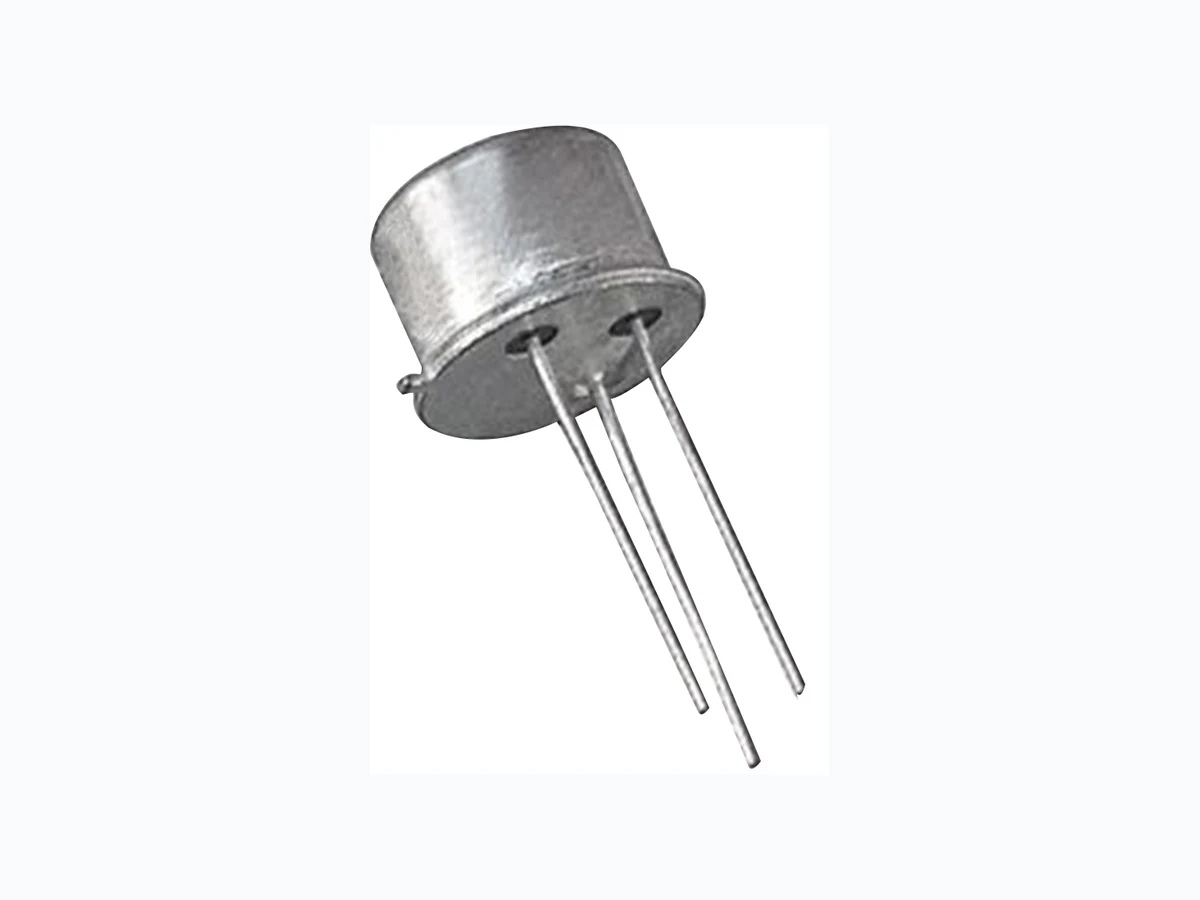
2N3440 MULTICOMP
Document overview
- Manufacturer or author: Provided By digicamel.com
- PDF pages: 2
Technical content
Page <1> V1.012/09/19 High Voltage Transistor Newark.com/multicomp-pro Farnell.com/multicomp-pro Element14.com/multicomp-pro Features:
- NPN High Voltage Silicon Transistor
- High Voltage Silicon Planar Transistors used in High Voltage and High Power Amplifier Applications Absolute Maximum Ratings: (Ta = 25°C unless otherwise specified) Characteristic Symbol Value Unit Collector Base Voltage VCBO 300 VCollector-Emitter Voltage VCES 250 Emitter-Base Voltage VEBO 7 Collector Current Continuous IC 1 A Base Current IB 0.5 Power Dissipation at Ta = 25°C Derate above 25°C PD 5.7 W mW/°CPower Dissipation at TC = 25°C Derate above 25°C 28.6 Operating Temperature TJ 200 Storage Temperature Range Tstg -65 to +200 Thermal Resistance Junction to Ambient Rth(j-a) 175 °C/W Junction to Case Rth(j-c) 35 Pin Configuration 1. Emitter 2. Base 3. Collector
Page <2> V1.012/09/19 High Voltage Transistor Newark.com/multicomp-pro Farnell.com/multicomp-pro Element14.com/multicomp-pro Description Part Number Transistor, NPN, TO-39 2N3440 Part Number Table Dimensions : Millimetres Dim. Min. Max. A 8.5 9.39 B 7.74 8.5 C 6.09 6.6 D 0.4 0.53 E - 0.88 F 2.41 2.66 G 4.82 5.33 H 0.71 0.86 J 0.73 1.02 K 12.7 - L 42° 48° TO-39 Metal Can Package Parameter Symbol Test Condition Unit Collector-Emitter Voltage VCEO(sus)* IC = 50mA, IB = 0 250 V Collector-Cut off Current ICBO VCB = 250V, IE = 0 <20 µA ICEO VCE = 200V, IB = 0 <50 ICEX VCE = 300V, VBE = 1.5V <500 Emitter-Cut off Current IEBO VEB = 6V, IC = 0 <20 DC Current Gain hFE* IC = 20mA, VCE = 10V 40 - 160 - Collector Emitter Saturation Voltage VCE(sat)* IC = 0.05A, IB = 4mA <0.5 V Base Emitter Saturation Voltage VBE(Sat)* IC = 50mA, IB = 4mA <1.3 Small Signal Characteristics Small Signal Current Gain hfe IC = 5mA, VCE = 10V, f = 1kHz >25 - Output Capacitance Cob VCB = 10V, IE = 0, f = 1MHz <10 pF Input Capacitance Cib VEB = 5V, IC = 0, f = 1MHz <75 Current Gain-Bandwidth Product ft IC = 10mA, VCE = 10V, f = 5MHz >15 MHz Real Part of Input impedance Re(hie) VCE = 10V, IC = 5mA, f = 1MHz <300 Ω Electrical Characteristics: (Ta = +25°C unless otherwise specified) *Pulse Test: Pulse Width = 300μs, Duty Cycle = 2% Pin Configuration 1. Emitter 2. Base 3. Collector Important Notice : This data sheet and its contents (the “Information”) belong to the members of the AVNET group of companies (the “Group”) or are licensed to it. No licence is granted for the use of it other than for information purposes in connection with the products to which it relates. No licence of any intellectual property rights is granted. The Information is subject to change without notice and replaces all data sheets previously supplied. The Information supplied is believed to be accurate but the Group assumes no responsibility for its accuracy or completeness, any error in or omission from it or for any use made of it. Users of this data sheet should check for themselves the Information and the suitability of the products for their purpose and not make any assumptions based on information included or omitted. Liability for loss or damage resulting from any reliance on the Information or use of it (including liability resulting from negligence or where the Group was aware of the possibility of such loss or damage arising) is excluded. This will not operate to limit or restrict the Group’s liability for death or personal injury resulting from its negligence. Multicomp Pro is the registered trademark of Premier Farnell Limited 2019.