
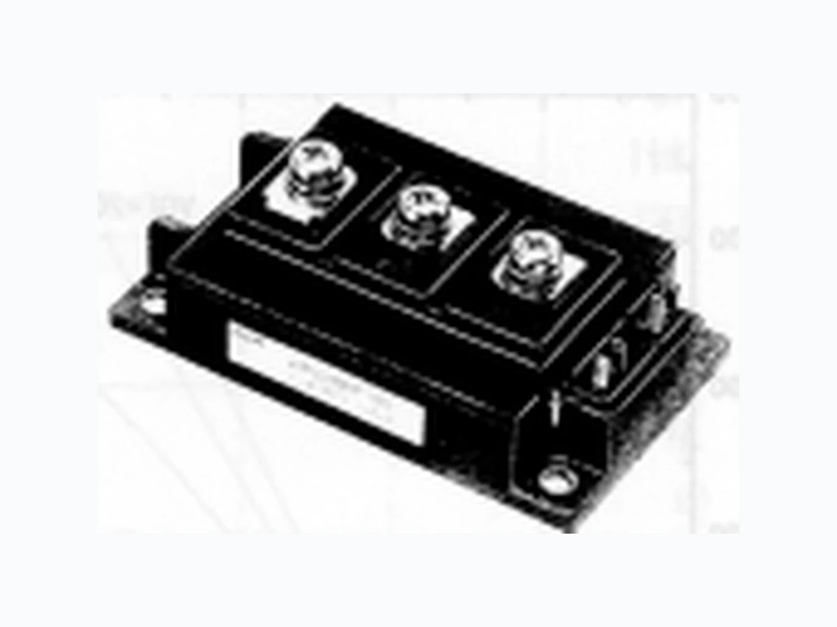
2MBI200PB-140_04 FUJI
Document overview
- Manufacturer or author: Provided By digicamel.com
- PDF pages: 4
Technical content
Features
- Small temperature dependence of the turn-off switching loss
- Easy to connect in parallel
- Wide RBSOA (square up to 2 time of rated current) and high short- circuit withstand capability
- Low loss and soft-switching (reduction of EMI noise) Thermal resistance characteristics Thermal resistance Contact Thermal resistance – – 0.085 – – 0.180 – 0.025 – IGBT Diode the base to cooling fin °C/W °C/W °C/W Equivalent Circuit Schematic Rth(j-c) Rth(j-c) Rth(c-f)* IGBT Module P-Series *4 : This is the value which is defined mounting on the additional cooling fin with thermal compound. G1 E1 G2 E2 C2E1 Items Symbols Conditions Characteristics Unit Min. Typ. Max. Item Zero gate voltage collector current Gate-Emitter leakage current Gate-Emitter threshold voltage Collector-Emitter saturation voltage Input capacitance Output capacitance Reverse transfer capacitance Turn-on time Turn-off time Diode forward on voltage Reverse recovery time I CES IGES VGE(th) VCE(sat) Cies Coes Cres ton tr toff tf VF trr – – 2.0 – – 400 6.0 8.0 9.0 – 2.7 3.0 – 3.3 – – 20000 – – 3000 – – 1300 – – – 1.20 – – 0.60 – – 1.00 – – 0.30 – 2.4 3.3 – – 0.35 VGE=0V, VCE=1400V VCE=0V, VGE=±20V VCE=20V, IC=200mA VGE=15V, IC=200A, Tj=25°C VGE=15V, IC=200A, Tj=125°C VCE=10V VGE=0V f=1MHz V CC=600V IC=200A VGE=±15V RG= 4.7 Ω IF=200A, VGE=0V IF=200A mA nA V V pF µs V µs Electrical characteristics (at Tj=25°C unless otherwise specified) Symbols Conditions Characteristics Unit Min. Typ. Max. Maximum ratings and characteristics Absolute maximum ratings (at Tc=25°C unless otherwise specified) *1 : All terminals should be connected together when isolation test will be done. *2 : Recommendable value : 2.5 to 3.5 N·m(M5) *3 : Recommendable value : 3.5 to 4.5 N·m(M6) Item Symbol Collector-Emitter voltage V CES Gate-Emitter voltage V GES Collector current I C ICp -IC -IC pulse Collector Power Dissipation P C Junction temperature T j Storage temperature T stg Isolation voltage between terminal and copper base *1 V iso Screw Torque Mounting * 2 Terminals *3 Rating 1400 ±20 300 200 600 400 200 400 1500 +150 -40 to +125 2500 3.5 4.5 Unit V V A W VAC N·m Conditions Continuous 1ms 1 device AC:1min. Tc=25°C Tc=80°C Tc=25°C Tc=80°C
Applications
- General purpose inverter
- AC and DC Servo drive amplifier
- Uninterruptible power supply
Characteristics (Representative)
Outline Drawings, mm M235