

 Download PDF
2DE19P ITT
Document overview
- Manufacturer or author: Provided By digicamel.com
- PDF pages: 11
Technical content
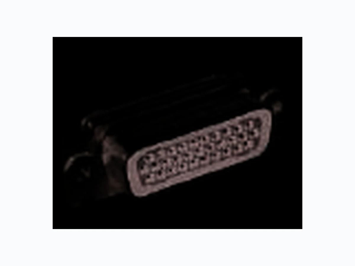
www.ittcannon.com Dimensions shown in inch (mm) Specifications and dimensions subject to change The Centi Line - .075" Contact Spacing Standard Data The Cannon Centi connectors are especially suitable for commercial applications such as computers, instrumentation, communications and audio equipment. They are available in D subminiature size metal shell rectangular, plas- tic shell rectangular and strip configurations. All Centi connectors use the reliable twist pin contact design in a 5 amp version terminated Centi contact is crimp removable, connectors are available for customer assembly. Standard crimp and assembly tools are available. The twist pin contact is recessed within the insulator housing while the rugged cylindrical socket is exposed. When the connector halves are mated, the chamfered sockets guide the pins into positive alignment. The CentipinTM contact, now under compression, forms a multi-point contact with the CentisocketTM to provide a high degree of reliability.
- Contact rating: 5 amps max, except BR Series (2 amps max.)
- Minimum contact centers: 0.075 (1.91).
- Wire sizes: #22 thru #26 AWG, stranded or solid.
- Contact termination: Multiple indent crimp.
- Contact retention: Crimp snap-in/removable.
- Contact materials and finish: Copper alloy, gold- plated per ASTM B488, Type II, Code C, Class 1.25.
- Mating/unmating force: 12 oz. per contact, max. Performance Data Test Method 301: 1,000 VAC at sea level
300 VAC at 70,000' altitude
Method 302, Condition A Method 107, Condition A +55˚C to +85˚C Method 213, Condition I:
100 G's, 3 axes, 6 millisecond
Method 204, Condition B:
15 G's, 10-2,000 Hz, 12 hours
unmating, 500 CPH max. Method 106, Omit 7a and 7b Method 101, Condition B: 48 hours Method 307: At 5 amps No breakdown No breakdown 5,000 megohms minimum No physical damage No physical damage No loss of continutiy> 1/µsec No physical damage No loss of continuity> 1µsec No mechanical or electrical defects Insulation resistance > 100 megohms Shall be capable of mating and unmating and meet contact resistance requirements 9 milliohms maximum 4 lb. minimum axial load (after 10 insertion extraction cycles) Dielectric Withstanding Voltage Insulation Resistance Thermal Shock Physical Shock Vibration Durability Moisture Resistance Salt Spray Contact Resistance Contact Retention Method Criteria of Acceptance
NOTE: Connectors may be ordered less contacts by adding the mod callout "FO" at end of number. Contacts are then supplied in bulk form. * Accommodates AWG #26 thru #22 E AF S PB R * * * * SERIES 2D - Double Density D 19, 31, 52, 79 and 100 BR - 90˚ right angle PCB mounting (For BR Series use "P" to designate jackpost) F171 - Jackpost assembly F172 - Standard jackscrew F173 - Low profile jackscrew For other modifications consult factory P - Pin S - Socket E, A, B, C and D Omit if not required SHELL SIZE SHELL SIZE FLOAT MOUNTS FLOAT MOUNTS CONTACT ARRANGEMENT CONTACT ARRANGEMENT CONTACT TYPE CONTACT TYPE* TERMINATION TERMINATION MODIFICATION MODIFICATION RoHS COMPLIANCE R Double Density D - .075" Contact Spacing 2D The Double Density D is a rectangular connector in the popular D Subminiature shell configuration featuring double the contact density in the same insert area. The Double Density D connector can thus accommodate up to 100 contacts instead of 50. This double contact density is achieved by using field-proven, highly reliable CentipinTM/CentisocketTM contacts on .075 (1.91) centers, in the positive con- tact alignment design. In this design contact positions are reversed; the flexible CentipinTM contacts are recessed in the insulator and the more rugged CentisocketTM contacts are exposed. This reversal of positions, and the chamfered-entry of the sockets, assures positive mating even under severe misalignment conditions. The contacts are retained in the monobloc insulator by a resilient internal shoulder that snaps into a locking groove in the con- tact. The chamfered front of the contact will not damage the internal shoulder in the insulator. Contacts are crimp removable type. The Double Density D connector is available in the five popular shell and insert sizes accommodating up to 100 contacts. These connectors mate exclusively with other Double Density D connectors. A wide range of accessories can be used, including junction shells, potting cups, switching shells, guide pin plates, and dust caps. 1. STANDARD D HARDWARE- 2. ONE PIECE MONOBLOCK INSULATOR- Including full range of D-Subminiature accessories glass-filled nylon material thermoplastic internal shoulder snaps into a locking groove in the contact. seven outer wiping surfaces assure electrical continuity even under severe shock and vibration flexible pin is recessed in insulator cavity and rugged socket is exposed assure alignment during mating and prevent scooping 3. CONTACT RETENTION- 4. TWIST PIN CONTACTS- 5. POSTIVE CONTACT ALIGNMENT- 6. GUIDE-IN KEYS AND KEYWAYS- Specifications WEIGHT Part Number by shell size 2DE19P 2DE19S 2DA31P 2DA31S 2DB52P 2DB52S 2DC79P 2DC79S 2DD100P 2DD100S 4.05 3.75 5.20 4.90 8.75 7.15 11.70 9.70 12.85 10.95 5.02 5.17 6.78 7.22 11.40 11.05 15.73 15.62 17.95 18.45 .142 .133 .183 .173 .308 .252 .413 .342 .453 .386 *Shell Mounting Hardware and Float Mounts Insulator Contacts Alternate finish, Modification Code Steel, cadmium plated with yellow chro- mate supplementary coating Stainless steel Glass-filled nylon Copper alloy, gold plate A106 Gold over brass A156 Gold over brass A197 Tin/Lead over steel Sizes Coupling Polarization Contact Spacing Contact Termination - Five shell sizes: E, A, B, C, and D - Friction or jackscrew - Keystone-shaped shells - .075 (1.91) - Crimp snap-in *Brass non-magnetic also available .177 .182 .239 .255 .402 .390 .555 .551 .633 .651 Weight (in gr.) Less With Contacts Weight (in oz.) Less With Contacts MATERIALS AND FINISHES MECHANICAL FEATURES www.ittcannon.com Dimensions shown in inch (mm) Specifications and dimensions subject to change
www.ittcannon.com Double Density D - .075" Contact Spacing 2D Standard Shell + + Part Number by Shell Size 2DE19P 2DE19S 2DA31P 2DA31S 2DB52P .250 (6.35) .250 (6.35) .250 (6.35) .250 (6.35) .236 (5.99) 2DB52S 2DC79P 2DC79S 2DD100P 2DD100S .236 (5.99) .236 (5.99) .236 (5.99) .236 (5.99) .236 (5.99) T + .020 (0.51) - .000 (0.00) Part Number by Shell Size T + .020 (0.51) - .000 (0.00) A B C T .856(21.74)MAX. D M K L J V G H TWO MTG. HOLES .123 ± .005 (3.12 ± 0.13) E 10˚ (TYP) Float Mount + + ++ TWO MTG. HOLES .0885 ± .0025 (2.248 ± 0.064) G H A B 10˚ (TYP) C D E K J N M .032 (.812) TOTAL DIAMETRAL FLOAT VPart Number by Shell Size A ± .015 (0.38) E ±.015 (0.38) B ± .010 (0.25) C ± .010 (0.25) D ± .010 (0.25) G ± .010 (0.25) H ± .010 (0.25) J ± .010 (0.25) K ± .010 (0.25) L ± .010 (0.25) M ± .010 (0.25) N ± .010 (0.25) V Max. 2DE19P 2DE19S 2DA31P 2DA31S 2DB52P 2DB52S 2DC79P 2DC79S 2DD100P 2DD100S 1.213 (30.81) 1.213 (30.81) 1.541 (39.14) 1.541 (39.14) 2.088 (53.03) 2.088 (53.03) 2.729 (69.31) 2.729 (69.31) 2.635 (66.92) 2.635 (66.92) .697 (17.70) .640 (16.26) 1.025 (26.03) .968 (24.58) 1.583 (40.21) 1.508 (38.30) 2.231 (56.67) 2.156 (54.76) 2.127 (54.02) 2.062 (52.37) .984 (24.99) .984 (24.99) 1.312 (33.32) 1.312 (33.32) 1.852 (47.04) 1.852 (47.04) 2.500 (63.50) 2.500 (63.50) 2.406 (61.11) 2.406 (61.11) .360 (9.14) .308 (7.82) .360 (9.14) .308 (7.82) .378 (9.60) .308 (7.82) .378 (9.60) .308 (7.82) .484 (12.29) .420 (10.67) .494 (12.55) .494 (12.55) .494 (12.55) .494 (12.55) .494 (12.55) .494 (12.55) .494 (12.55) .494 (12.55) .605 (15.37) .605 (15.37) .759 (19.28) .759 (19.28) 1.083 (27.51) 1.083 (27.51) 1.625 (41.27) 1.625 (41.27) 2.272 (57.71) 2.272 (57.71) 2.178 (55.32) 2.178 (55.32) .422 (10.72) .422 (10.72) .422 (10.72) .422 (10.72) .422 (10.72) .422 (10.72) .422 (10.72) .422 (10.72) .534 (13.56) .534 (13.56) .036 (.914) .032 (213) .036 (.914) .032 (213) .036 (.914) .032 (213) .036 (.914) .032 (213) .036 (.914) .032 (213) .236 (5.99) .243 (6.17) .236 (5.99) .243 (6.17) .231 (5.87) .243 (6.17) .231 (5.87) .243 (6.17) .231 (5.87) .243 (6.17) .055 (1.40) .047 (1.19) .055 (1.40) .047 (1.19) .055 (1.40) .047 (1.19) .055 (1.40) .047 (1.19) .055 (1.40) .047 (1.19) .422 (10.72) .429 (10.90) .422 (10.72) .429 (10.90) .426 (10.82) .429 (10.90) .426 (10.82) .429 (10.90) .426 (10.82) .429 (10.90) .120 (3.05) .120 (3.05) .120 (3.05) .120 (3.05) .129 (3.28) .120 (3.05) .129 (3.28) .120 (3.05) .129 (3.28) .120 (3.05) .555 (14.10) .555 (14.10) .555 (14.10) .555 (14.10) .555 (14.10) .555 (14.10) .555 (14.10) .555 (14.10) .555 (14.10) .555 (14.10) For shell with float mounts, add letter F after shell size, e.g., 2DEF19P. Jackscrew/Jackpost Assembly #4-40 UNC-2A THREAD #4-40 UNC-2A THREAD #4-40 UNC-2A THREAD #4-40 UNC-2B THREAD .233 (5.92) .223 (5.66) .325 ± .015 (8.26 ± 0.38) .025 (0.64) MAX. .025 (0.64) MAX. .180 ± .025 Grip (4.57 ± 0.64) Length .180 ± .025 Grip (4.57 ± 0.64) Length (15.75 ± 0.25) Standard (F172) Jackscrew (factory installed) Low Profile (F173) Jackscrew (factory installed) Jackpost (F171) Front Panel Connector Mounting Only Dimensions shown in inch (mm) Specifications and dimensions subject to change
www.ittcannon.com Double Density D - .075" Contact Spacing 2D Dimensions shown in inch (mm) Specifications and dimensions subject to change Contact Arrangements DE
19 Contacts
All views are pin front face. Use reverse order for socket side. Cavity identification numbers are shown for reference only and do not appear on insulator front face. However they do appear on rear of insulator. 100 DA
31 Contacts
52 Contacts
100 Contacts
79 Contacts
90˚ PCB Mounting - 3 Row .148 (3.76) MIN. .253 (6.43) .233 (5.92) .130 (3.30) .100 (2.54) .125 (3.18) .115 (2.92) DIA. TYP. .0375 (0.95) REF. .075 (.190) REF. .690 (17.53) MAX. .510 (12.95) .490 (12.45) .510 (12.95) .480 (12.18) CAV. #1 .065 (1.65) #4-40 UNC-2B THREAD (2 PLACES) LAST LEAD PCB Termination Leads (all contact arrangements) Suggested finished PC hole LEAD #1 LAST CAV. B A A .075 (1.90) .100 (2.54) REF. .100 (2.54) REF. B Part Number by Shell Size A ± .015 (0.38) B ± .010 (0.25) C Max. 2DE19SBRP 2DA31SBRP 2DB52SBRP 2DC79SBRP 1.215 (30.86) 1.540 (39.12) 2.090 (53.09) 2.730 (69.34) .984 (24.99) 1.312 (33.32) 1.852 (47.04) 2.500 (63.50) .690 (17.53) .690 (17.53) .690 (17.53) .690 (17.53)
www.ittcannon.com Dimensions shown in inch (mm) Specifications and dimensions subject to change 90˚ PCB Mounting - 4 Row +++ + + + +++ + + + ++++ + + + +++ ++ + + +++ +++ + + + + ++ + + + + ++ + + + + + ++ + + + ++ +++ + + + + + + + + + + +++ + + .130 (3.30) MIN. .253 (6.43) .233 (5.92) .790 (20.07) MAX. .125 (3.18) .115 (2.92) DIA. TYP. .510 (12.95) .490 (12.45) .065 (1.65) .620 (15.75) .590 (14.99) .075 (1.90) CAV #100 A A LEAD #100 Part Number by Shell Size 2DD100SBRP A +_ .015 (0.38) B +_ .010 (0.25) C Max. Contact Arrangements - Page 62 LEAD CAV #1 #4-40 UNC-2B THREAD (2 PLACES) B B .0375 (0.94) REF. .075 (1.90) REF. .100 (2.54) REF. .100 (2.54) REF. .200 (5.08) REF. Double Density D - .075" Contact Spacing 2D
www.ittcannon.com Dimensions shown in inch (mm) Specifications and dimensions subject to change Double Density D - .075" Contact Spacing 2D Panel Cutouts G B A F E K TYP RFULL R D C C DG .032 (0.81) R MAX. TYP 10˚0' TYP. H Mtg. Method A +_ .005 (0.13) B +_ .005 (0.13) C +_ .005 (0.13) D +_ .005 (0.13) E +_ .005 (0.13) F +_ .005 (0.13) G +_ .002 (0.05) H +_ .002 (0.05) K 2DE 2DA 2DB 2DC 2DD Front Rear Front Rear Front Rear Front Rear Front Rear .874 (22.20) .806 (20.47) 1.202 (30.53) 1.134 (28.80) 1.743 (44.27) 1.674 (42.52) 2.391 (60.73) 2.326 (59.08) 2.297 (58.34) 2.218 (56.34) .437 (11.10) .403 (10.24) .601 (15.26) .567 (14.40) .872 (22.15) .837 (21.26) 1.196 (30.38) 1.163 (29.54) 1.149 (29.18) 1.109 (28.17) .984 (24.99) .984 (24.99) 1.312 (33.32) 1.312 (33.32) 1.852 (47.04) 1.852 (47.04) 2.500 (63.50) 2.500 (63.50) 2.406 (61.11) 2.406 (61.11) .492 (12.50) .492 (12.50) .656 (16.66) .656 (16.66) .926 (23.52) .926 (23.52) 1.250 (31.75) 1.250 (31.75) 1.203 (30.56) 1.203 (30.56) .513 (13.03) .449 (11.40) .513 (13.03) .449 (11.40) .513 (13.03) .449 (11.40) .513 (13.03) .449 (11.40) .623 (15.82) .555 (14.10) .257 (6.53) .225 (5.71) .257 (6.53) .225 (5.71) .257 (6.53) .225 (5.71) .257 (6.53) .225 (5.71) .312 (7.92) .278 (7.06) .120 (3.05) .120 (3.05) .120 (3.05) .120 (3.05) .120 (3.05) .120 (3.05) .120 (3.05) .120 (3.05) .120 (3.05) .120 (3.05) .060 (1.52) .060 (1.52) .060 (1.52) .060 (1.52) .060 (1.52) .060 (1.52) .060 (1.52) .060 (1.52) .060 (1.52) .060 (1.52) .083 (2.11) .132 (3.35) .083 (2.11) .132 (3.35) .083 (2.11) .132 (3.35) .083 (2.11) .132 (3.35) .083 (2.11) .132 (3.35) For contact part numbers, termination tooling and assembly see pages 67-69. Panel Mounting 3/32 THICKNESS (REF.) RECOMMENDED RIVET THICKNESS RIVET THICKNESS Front Mounting Standard Rear Mounting Standard Front Mounting Float Rear Mounting Float
www.ittcannon.com Centi-D Loc-.075" Contact Spacing CDL How to Order A subminiature all plastic high density "D" rectan- gular connector. The CDL is a general purpose connector with a peripheral o-ring and wire sealing gasket. Connector utilizes rear insertion, fr ont re- lease, crimp snap-in size 22, centi-loc contacts installable by the custormer or, if preferred, by the factory. MATERIAL Insulator: Dielectric Gasket: Contact: Seal Ring Black Nylon Polychloroprene Copper Alloy, Gold Plated Silicone SERIES SERIES Centi-D Loc Series 139 (Consult customer service for other sizes) P - Centi-loc pin S - Centi-loc socket F0 - Less contacts - No lock (mtg. holes) - No lock type with rear gasket CONTACT ARRANGEMENT CONTACT STYLE MODIFICATION CODES TYPE CDL 2A 139 F0 P *- -- TYPE CONTACT ARRANGEMENT CONTACT STYLE MODIFICATION CODES RoHS COMPLIANCE R Plug 2.344 (59.54) ± .005 (0.13) .625 (15.88) ± .010 (0.25) .260 (6.60) ± .010 (0.25) .540 (13.72) MAX. .150 (3.81) ± .010 (0.25) 2.025 (51.44) MAX. Plug Receptacle SILICONE SEAL RING CONTACT HEIGHT .035 (0.89) .015 (0.38) 2.625 (66.68) .560 (14.22) MAX. CAVITY #1 .625 (15.88) ± .010 (0.25) .175 (4.44) MAX. CONTACT HEIGHT .065 (1.65) .045 (1.14) .535 (13.59) MAX. .150 (3.81) ± .010 (0.25) 2.025 (51.44) MAX. CAVITY #1 Recommended Panel Cutouts .125 (3.18) DIA. TYP. .565 (14.35) ± .005 (0.13) .2035 (51.69) RAD. MAX. 2.344 (59.54) ± .005 (0.13) Contact Arrangements Plug Receptacle CAVITY #1 CAVITY #1 CAVITY #70 Engaging Face View CAVITY #70 CAVITY #117 CAVITY #117 CAVITY #92 CAVITY #92 CAVITY #139 CAVITY #139 Dimensions shown in inch (mm) Specifications and dimensions subject to change
Strip Connectors - .100"/.075" Contact Spacing CTA Components and Accessories www.ittcannon.com CENTI-LOC connectors are low-cost nylon strip connectors designed for commercial applications such as instrumentation, commu- nications, and medical equipment. They are available in continuous strip form up to a max- imum length of 6 inches (152.40mm), accom- modating from 1 to 60 rear insertion, front release, crimp snap-in size 22 CENTIPIN TM/ CENTISOCKETTM contacts. These contacts utilize a proven positive contact alignment design, giving additional contact strength and positive contact alignment during mating. These connectors can be ordered in kit or bulk form. The kit comprises all the parts necessary to assemble one complete 6-inch (152.40) strip connector with 60 contacts on .100 (2.54) cen- ters or a 4-inch (101.60mm) strip with 53 con- tacts on .075 (1.91) centers. If more then one connector is required, the parts can be ordered in bulk and assembled as desired. The CENTI-LOC strip connector can be ordered in kit or bulk form. The kit includes matin g insulators with a full compliment of contacts and two guide posts. If more than one connector is required, the parts can be ordered in bulk and assembled as desired. The guide posts and polarizing posts are inserted in the same manner as the contacts. The guide posts are inserted into the socket insulator and the polarizing posts are inserted into the pin insulator. The corresponding contact in the mating insulator must be removed for each. See assembly instructions. Kit Form Insulator Part Number CT A3-KIT CT A4-KIT CT A3-CT A4-KIT Part Number Contact Center Spacing T ype Material CT A3-IP-53 CT A3-IS-53 CT A4-IP-60 CT A4-IS-60 CT A-GP CT A-PP .075 (1.91) .075 (1.91) .100 (2.54) .100 (2.54) Pin Socket Pin Socket P/N 230-9507-000 P/N 230-9506-000 Nylon Nylon Nylon Nylon Passivated Stainless Steel Passivated Stainless Steel Insulator Guide Post Polarizing Post .075 (1.91) .100 (2.54) Contact Center spacing Guide Posts Polarizing Posts .475 (12.06) MAX..275 (6.98) MAX. Kits include mating insulators with full complement of contacts and two guide posts. Dimensional Data Weights CTA3-.075(1.91) Centers C TA4-.100(2.54) Centers 4.031 (102.39) MAX. .115 (2.92) MAX. .115 (2.92) MAX. .100 (2.54) TYP. 6.031 (153.19) MAX. .075 (1.91) TYP. Part Number No. of Contacts Contacts Type Avy. Weight oz. ± 5% gm. pin socket pin socket .185 .203 .230 .241 5.25 5.75 6.30 6.90 CTA3 CTA4 Dimensions shown in inch (mm) Specifications and dimensions subject to change
www.ittcannon.com Dimensions shown in inch (mm) Specifications and dimensions subject to change The Centi Line - .075" Contact Spacing 2D/CTA Contacts A resilient internal shoulder retains the contacts in the insulator housing. The front of the contact is chamfered to prevent damage to the internal shoulder as the contact is pushed into position. Subtract .064 (1.63) + _ .010 (.25) from pigtail length when used in 2D pin insulator for potting well of connector assembly. Subtract .081 (2.08) + _ .010 (.25) from pigtail length when used in 2D socket insulator for potting well of connector assembly. Contact Part Number Part Number Pin 031-9540-000 031-9540-004 031-9540-005 030-9542-001 030-9542-002 030-9542-004 Standard 30µin. plating 50µ in. plating 50µ in. plating NOTE: Plating, except as noted, is 30 micro-inch gold. Consult factory for any tail size or plating requirements. Special crimp locator required. Part number: 995-0001-714. (L3198-CL-PSL) Use special insertion tip (323-9510-016 &-017). * With inspection hole; 50µ in. plating P.C. tail N/A 030 -9542-011 P.C. tail .020 dia. x 030-9542-012 Long crimp barrel 030-9542-014 Small crimp bore For AWG #32 & 30 030-9556-000 *** Small crimp bore For AWG #28 & 30 030-9542-022 .183 lg. Soc. .183 lg. Pin P.C. tail .020 dia. x 030-9542-015 P.C. tail .018 dia. x 030-9542-016 *031-9540-013 031-9540-016 031-9540-022 *** 031-9540-007 *031-9540-015 *031-9540-019 .232 lg. Soc. .255 lg. Pin .444 lg. Soc. .445 lg. Pin Socket Type Pin Socket P.C. Tail Contacts 2D and Centi-Loc Crimp and Assembly Tools Insertion Tools For Standard Contact Insertion Tools For Long Crimp barrel Contacts Extraction Tools Tool M22520/2-01 CIET-CTA Handle CTA-AB Assembly Holding Block Part Number: 328-9508-000 Socket Extraction Tip Pin Extraction Tip Insertion Tips
Description
Size* 30/P .C. Tail AWG Size* Tip Part Number * Pin Contact Tip Part Number * Socket Contact Contact CENTIPIN CENTISOCKET (handle and tip) Tip Part Number Handle Part Number 070112-0002 070113-0001 324-9502-000 324-9501-000 204-9500-000 204-9500-000 Handle Part Number* 204-9500-000 204-9500-000 204-9500-000 323-9510-008 323-9510-009 323-9510-010 323-9510-012 323-9510-013 323-9510-014 Based on wire size per MIL-W-16878 with Type E insulation, use smaller tool for wire with thin insulation, larger tool for wire having thick insulation. The 5 insertion tips (part numbers 323-9510-001 thru - 005). plus handle, and the pin and socket extaction tips maybe ordered as a SINGLE KIT by specifying the part number CIET-CTA-2. [Part number: 070143-0002]. To order the SINGLE KIT for the long crimp barrel contact (tip part numbers 323-9510-008 thru -014, handle and pin and socket extraction tips) please specify CIET-CTA-3. * CIT-PS-CTA-22 CIT-PS-CTA-24 CIT-PS-CTA-26 CIT-PS-CTA-28 CIT-PS-CTA-30 323-9510-001 323-9510-002 323-9510-003 323-9510-004 323-9510-005 204-9500-000 204-9500-000 204-9500-000 204-9500-000 204-9500-000 Kit Part Number (handle and tip) Tip Part Number Handle Part Number M22520/2-01 995-0001-584 L3198-CLP 995-0001-338 L3198-CLS 995-0001-353 Pin Socket Locators
The Centi Line - .075" Contact Spacing 2D/CTA 2D/CTA CENTI-LOCTM Connectors Assembly Instructions www.ittcannon.com The Double Density D/CTA CENTI-LOC Connectors are highly reliable and simple connectors to use. There are a few helpful suggestions that will assure complete satisfaction when followed: 1. The following instructions should be followed. 2. The proper crimp tool and locator (if required) must be used. These tools have been designed for use with this product. Substitutions of crimp- ing equipment may result in connector failure at the assembly operation. 3. After crimping a contact to a lead it is of vital importance that the proper tool be used to assure seating the contact in the insulator in the proper position. Any substitution of insertion tools may result in over or under insertion of the contact which may damage the retention system of the insulator. 4. The female (socket) side of the connector has been designed with a controlled float to allow for ease of mating. To avoid reducing this float or causing a splaying of the contacts, any unneces- sary strain caused by clamping the leads too close to the rear of the connector should be avoided. Use of recommended tooling together with proper assembly techniques will pay dividends in reliability and reduced costs. 2D Assembly Instructions Cut the wires to length required and strip .100" of insulation from the end to be crimped. Check for cut or broken wires and frayed insulation. Using the proper crimp tool and locator, insert the contact into the locator. Insert the stripped end of the wire into the contact crimp pot, and crimp the contact to the wire. Squeeze the handles firmly to insure a proper crimp (tool will not release if crimping is incomplete). NOTE: Contact stop must be changed in tool locator when crimping pin and socket contacts. 1. Place the proper insertion tip in the insertion/-extraction handle and put the tip over the wire as shown. The tool tip will butt up against the crimp pot. Connector must be firmly supported during both insertion and extraction operations. 2. Using a firm, steady pressure, push the contact into the cavity until the resilient internal shoulder in the insulator snaps into the locking groove in the contact. The shoulder of the tool tip bottoms against the rear of the insulator, preventing over-insertion. Repeat for balance of contacts. 1. For contact extraction, remove the insertion tool tip and replace it with the proper extraction tool tip. (The socket tip will fit into the socket, and the pin tip will slide over the pin bundle). Insert the tool tip into the contact cavity: (the pin tip will butt up against the shoulder of the pin contact, and the socket tip will bottom out in the socket contact.) 2. Apply a firm, steady pressure until the contact is released from the internal shoulder in the insulator. The shoulder of the tool tip bottom against the insulator face to prevent damage to the internal shoulder. Remove the tool tip and pull the contact from the rear of the connector. Repeat for the balance of contacts to be removed. WIRE STRIPPING .100 (2.54) CONTACT INSERTION CONTACT EXTRACTION CONTACT CRIMPING Dimensions shown in inch (mm) Specifications and dimensions subject to change
www.ittcannon.com Dimensions shown in inch (mm) Specifications and dimensions subject to change The Centi Line - .075" Contact Spacing 2D/CTA CTA Assembly Instructions .275 (6.98) MAX. .475 (12.06) MAX. INSERTION Guide Posts Polarizing Posts 1. Place the connector into the slot in the assembly block with the arrows on the insulator pointing downward. The connector will bottom against the internal shoulder in the groove in the assembly block. Start contact insertion by placing the crimped contact in the cavity by hard. 3. With firm steady pressure, push the contact into the cavity until the resilient internal shoulder snaps into the locking groove in the contact. To prevent over insertion, the tool tip bottoms against the rear of the insulator. 4. The guide post and polarizing posts are inserted in teh same manner as the contacts. The guide posts are inserted into the socket insulator, and the polarizing posts are inserted into the pin insulartor. The corresponding contact in the mating insulator must be removed for each. 2. Position the insertion tool tip on the rear of contact as shown. The insulation must be pulled back from the crimp pot approximately 1/32" to allow the tool tip to butt against the contact crimp pot. EXTRACTION 1. To extract the contacts, place the conector face up in the assembly block so that the contact to be extracted is in the end of the block that has a fully slotted opening. 2. The pin extraction tool tip is tubular, slides over the pin bundle and butts against the front shoulder of the pin. The socket extraction tool is a solid rod that fits into the socket contact, the external shoulder butts against the contact socket shoulder. 3. Insert the extraction tool into the cavity and apply firm pressure until the contact is pushed thru the rear of the connector. 4. Lift the insulator from the groove and pull the contact out. Repeat for balance of contacts to be removed.