


 Download PDF
UFW0J331MPD NICHICON
Document overview
- PDF pages: 2
Technical content
Page 1
ALUMINUM ELECTROLYTIC CAPACITORS
FW series
Standard, For Audio Equipment
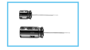
Adapted to the RoHS directive (2002/95/EC).
KW
High Sound Quality FW
FG High Grade
Specifications
| Item | Performance Characteristics |
| Category Temperature Range | –40 ~ +85°C |
| Rated Voltage Range | 6.3 ~ 100V |
| Rated Capacitance Range | 0.1 ~ 33000µF |
| Capacitance Tolerance | ± 20% at 120Hz, 20°C |
| Leakage Current | After 1 minute's application of rated voltage, leakage current is not more than 0.03 CV or 4 (µA) , whichever is greater. After 2 minutes' application of rated voltage, leakage current is not more than 0.01 CV or 3 (µA) , whichever is greater. |
| tan δ | Rated voltage (V) 6.3 10 16 25 35 50 63 100 Measurement frequency : 120Hz, tan δ (MAX.) 0.28 0.24 0.20 0.16 0.14 0.12 0.10 0.08 Temperature : 20°C For capacitance of more than 1000µF, add 0.02 for every increase of 1000µF. |
| Stability at Low Temperature | Measurement frequency : 120Hz Rated voltage (V) 6.3 10 16 25 35 50 63 100 Impedance ratio Z–25°C / Z+20°C 5 4 3 2 2 2 2 2 ZT / Z20 (MAX.) Z–40°C / Z+20°C 12 10 8 5 4 3 3 3 |
| Endurance | After 2000 hours' application of voltage at Capacitance change Within ±20% of initial value 85°C, capacitors meet the characteristic tan δ 200% or less of initial specified value requirements listed at right. Leakage current Initial specified value or less |
| Shelf Life | After sroring the capacitors under no load at 85°C for 1000 hours, and after performing voltage treatment based on JIS C 5101-4 clause 4.1 at 20°C, they will meet the specified value for endurance characteristics listed above. |
| Marking | Printed with black color letter on Gold sleeve. |
| Rated voltage (V) | 6.3 | 10 | 16 | 25 | 35 | 50 | 63 | 100 | |
| Impedance ratio ZT / Z20 (MAX.) | Z–25°C / Z+20°C | 5 | 4 | 3 | 2 | 2 | 2 | 2 | 2 |
| Z–40°C / Z+20°C | 12 | 10 | 8 | 5 | 4 | 3 | 3 | 3 | |
Radial Lead Type
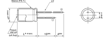
(mm)
| fD | 5 | 6.3 | 8 | 10 | 12.5 | 16 | 18 | 20 | 22 | 25 |
| P | 2.0 | 2.5 | 3.5 | 5.0 | 5.0 | 7.5 | 7.5 | 10 | 10 | 12.5 |
| fd | 0.5 | 0.5 | 0.6 | 0.6 | 0.6 | 0.8 | 0.8 | 1.0 | 1.0 | 1.0 |
| 0.5 | 0.5 | 0.5 | 0.5 | 0.5 | 0.5 | 0.5 | 0.5 | 1.0 | 1.0 |
(fD < 20) 1.5 (fD 20) 2.0
- Please refer to page 21 about the end seal configulation.
Please refer to page 21, 22, 23 about the formed or taped product spec.
Please refer to page 3 for the minimum order quantity.
Dimension table in next page.
Type numbering system (Example : 10V 1000µF)
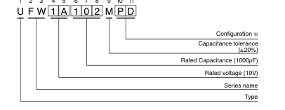
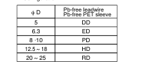
Configuration
CAT.8100V
Page 2
ALUMINUM ELECTROLYTIC CAPACITORS
FW series
Dimensions
| V Cap.(µF) Code | 6.3 | 10 | 16 | 25 | 35 | 50 | 63 | 100 | |||||||||
| 0J | 1A | 1C | 1E | 1V | 1H | 1J | 2A | ||||||||||
| 0.1 | 0R1 | 5 × 11 | 1.1 | 5 × 11 | 2.1 | ||||||||||||
| 0.22 | R22 | 5 × 11 | 2.4 | 5 × 11 | 4.7 | ||||||||||||
| 0.33 | R33 | 5 × 11 | 3.5 | 5 × 11 | 7.0 | ||||||||||||
| 0.47 | R47 | 5 × 11 | 5.0 | 5 × 11 | 10 | ||||||||||||
| 1 | 010 | 5 × 11 | 10 | 5 × 11 | 21 | ||||||||||||
| 2.2 | 2R2 | 5 × 11 | 23 | 5 × 11 | 30 | ||||||||||||
| 3.3 | 3R3 | 5 × 11 | 35 | 5 × 11 | 40 | ||||||||||||
| 4.7 | 4R7 | 5 × 11 | 40 | 5 × 11 | 45 | ||||||||||||
| 10 | 100 | 5 × 11 | 65 | 5 × 11 | 70 | 6.3 × 11 | 75 | ||||||||||
| 22 | 220 | 5 × 11 | 95 | 5 × 11 | 100 | 6.3 × 11 | 120 | ||||||||||
| 33 | 330 | 5 × 11 | 105 | 5 × 11 | 120 | 6.3 × 11 | 140 | 8 × 11.5 | 160 | ||||||||
| 47 | 470 | 5 × 11 | 115 | 5 × 11 | 120 | 6.3 × 11 | 150 | 6.3 × 11 | 165 | 10 × 12.5 | 210 | ||||||
| 100 | 101 | 5 × 11 | 145 | 5 × 11 | 155 | 6.3 × 11 | 185 | 6.3 × 11 | 200 | 8 × 11.5 | 250 | 10 × 12.5 | 300 | 10 × 20 | 350 | ||
| 220 | 221 | 6.3 × 11 | 230 | 6.3 × 11 | 250 | 8 × 11.5 | 320 | 10 × 12.5 | 370 | 10 × 12.5 | 410 | 10 × 16 | 470 | 12.5 × 25 | 600 | ||
| 330 | 331 | 6.3 × 11 | 265 | 6.3 × 11 | 270 | 8 × 11.5 | 360 | 10 × 12.5 | 420 | 10 × 12.5 | 470 | 10 × 16 | 570 | 10 × 20 | 650 | 12.5 × 25 | 750 |
| 470 | 471 | 6.3 × 11 | 310 | 6.3 × 11 | 330 | 8 × 11.5 | 420 | 10 × 12.5 | 530 | 10 × 16 | 630 | 12.5 × 20 | 760 | 12.5 × 20 | 880 | 16 × 25 | 1000 |
| 1000 | 102 | 8 × 11.5 | 530 | 10 × 12.5 | 630 | 10 × 16 | 770 | 10 × 20 | 950 | 12.5 × 20 | 1100 | 12.5 × 25 | 1300 | 16 × 25 | 1300 | 18 × 40 | 1370 |
| 2200 | 222 | 10 × 20 | 980 | 10 × 20 | 1050 | 12.5 × 20 | 1250 | 12.5 × 25 | 1550 | 16 × 25 | 1800 | 16 × 35.5 | 2090 | 18 × 35.5 | 2200 | 22 × 50 | 2400 |
| 3300 | 332 | 10 × 20 | 1170 | 12.5 × 20 | 1420 | 12.5 × 25 | 1700 | 16 × 25 | 1950 | 16 × 35.5 | 2220 | 18 × 35.5 | 2360 | 20 × 40 | 2700 | 25 × 50 | 2900 |
| 4700 | 472 | 12.5 × 20 | 1350 | 12.5 × 25 | 1800 | 16 × 25 | 2100 | 16 × 31.5 | 2360 | 18 × 35.5 | 2490 | 20 × 40 | 2900 | 22 × 50 | 3400 | ||
| 6800 | 682 | 12.5 × 25 | 1600 | 16 × 25 | 2150 | 16 × 35.5 | 2500 | 18 × 35.5 | 2590 | 20 × 40 | 3000 | 22 × 50 | 3500 | 25 × 50 | 3500 | ||
| 10000 | 103 | 16 × 25 | 2000 | 16 × 35.5 | 2500 | 18 × 35.5 | 2640 | 20 × 40 | 3000 | 22 × 50 | 3700 | 25 × 50 | 4000 | ||||
| 15000 | 153 | 16 × 35.5 | 2550 | 18 × 35.5 | 2720 | 20 × 40 | 3400 | 22 × 50 | 3800 | 25 × 50 | 4300 | ||||||
| 22000 | 223 | 18 × 40 | 3200 | 20 × 40 | 3700 | 22 × 50 | 4200 | 25 × 50 | 4500 | ||||||||
| 33000 | 333 | 22 × 50 | 3900 | 22 × 50 | 4500 | 25 × 50 | 4800 | Case size φD × L (mm) | Rated ripple | ||||||||
Rated Ripple (mArms) at 85°C 120Hz
Frequency coefficient of rated ripple current
| Frequency Cap.(µF) | 50Hz | 120Hz | 300Hz | 1kHz | 10kHz ~ |
| ~ 47 | 0.75 | 1.00 | 1.35 | 1.57 | 2.00 |
| 100 ~ 470 | 0.80 | 1.00 | 1.23 | 1.34 | 1.50 |
| 1000 ~ 33000 | 0.85 | 1.00 | 1.10 | 1.13 | 1.15 |