
 Download PDF
2904 RHOPOINT
Document overview
- PDF pages: 2
Technical content
Page 1
2900 Series/Microminiature Reed Relays
R REED EEDR RELAYS
MICROMINIATURE
REED RELAYS
ICROMINIATURE R
R EED R R
ICROMINIATURE ICROMINIATURE
EED ELAYS ELAYS ELAYS
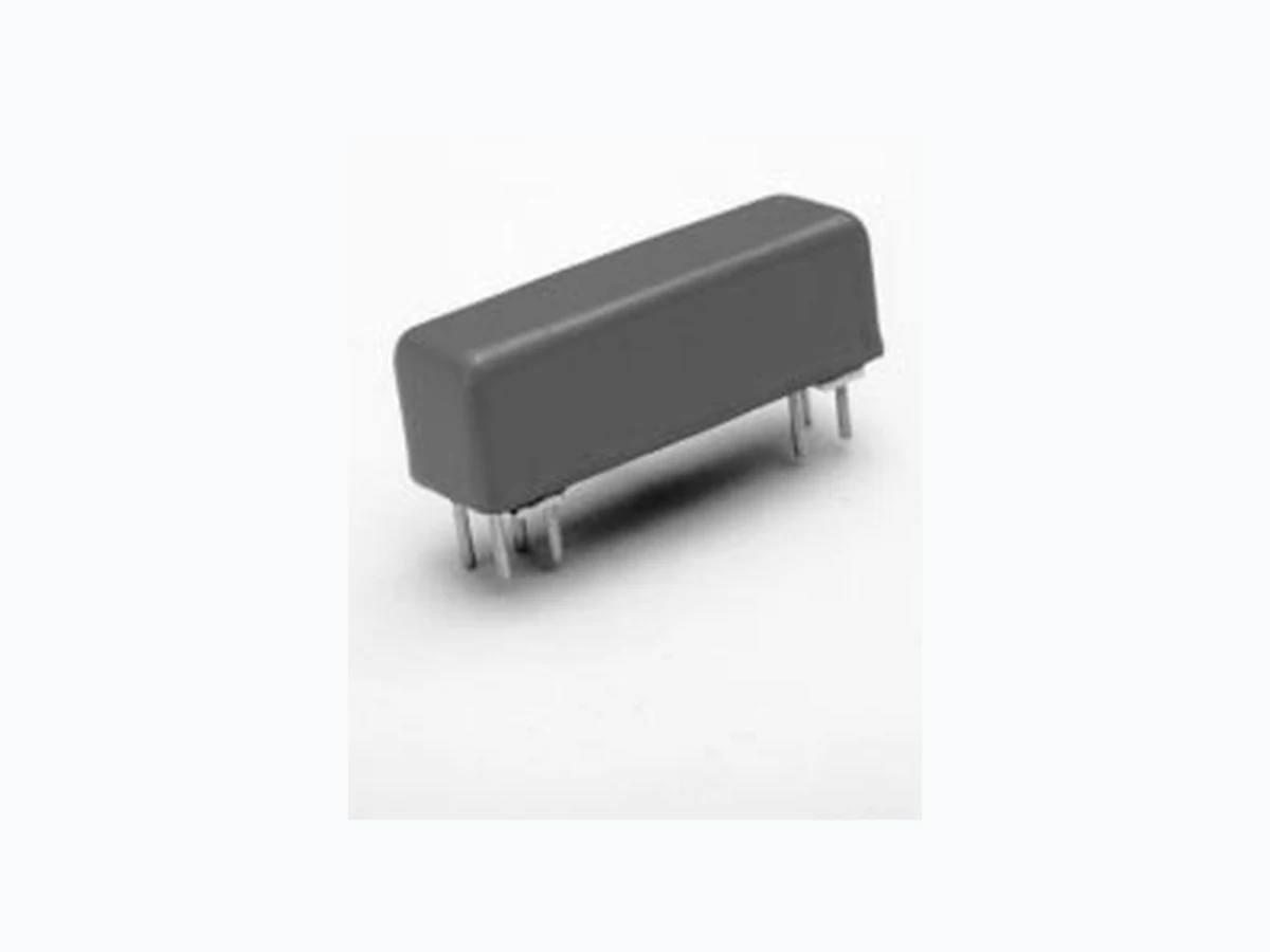
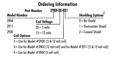
ICROMINIATURE Ideally suited to the needs of Automated Test Equipment and RF requirements. The specification tables allow you to select the appropriate relay for your particular application. Slightly larger than the 2200 Series; these relays provide maximum versatility with options such as electrostatic and coaxial shielding. If your requirements differ, please consult your local representative or Coto’s Factory.
2900 S 2900 SERIES F
F F F FEATURES
2900 SERIES 2900 S 2900 S ERIES EATURES ERIES EATURES EATURES EATURES ERIES u Very small (0.20 in2), high reliability reed relays. u High Insulation Resistance - 1012 Ω offered on some models. u High speed switching compared to electromechanical relays. u Hermetically sealed contacts for long life. u Epoxy coated steel shell provides magnetic shielding. u Optional Electrostatic Shield for reducing capacitive coupling. u Optional Coaxial Shield for 50 Ω impedance and switching of fast rise time digital pulses.
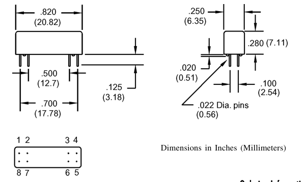
Bottom View
RHOPOINT COMPONENTS LTD Email: components@rhopoint.co.uk Website: www.rhopoint.co.uk
COTO TECHNOLOGY
Page 2
2900 Series/Microminiature Reed Relays
Model Number
2904 2
2911 2
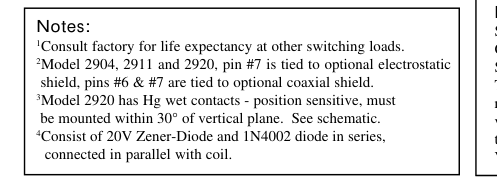
x 2920 2,3
Parameters
Test Conditions
Units
1 Form A
1 Form C 1 Form A Hg
Wet
COIL RESISTANCE
| Nom. Coil Voltage Coil Resistance Operate Voltage Release Voltage CONTACT RATING Switching Voltage Switching Current Carry Current Contact Rating Life Expectancy-Typical 1 Static Contact Resistance (max. init.) Dynamic Contact Resistance (max. init.) RELAY SPECIFICATIONS Insulation Resistance (minimum) Capacitance - Typical Across Open Contacts Dielectric Strength (minimum) Operate Time - including bounce - Typical Release Time - Typical | +/- 10%, 25° C Must Operate by Must Release by Max DC/Peak AC Resist. Max DC/Peak AC Resist. Max DC/Peak AC Resist. Max DC/Peak AC Resist. Signal Level 1.0V, 10mA 50mV, 10mA 0.5V, 50mA at 100 Hz, 1.5 msec Between all Isolated Pins at 100V, 25°C, 40% RH Shield Floating Shield Guarding Between Contacts Contacts to Shield Contacts/Shield to Coil At Nominal Coil Voltage, 30 Hz Square Wave Zener-Diode Suppression4 | VDC Ω VDC - Max. VDC - Min. Volts Amps Amps Watts x 106 Ops. Ω Ω Ω pF pF VDC/peak AC VDC/peak AC VDC/peak AC msec. msec. | 5 12 370 1500 3.8 9.0 0.4 1.0 200 0.5 1.5 10 500 0.100 0.200 x 10¹² 1.0 0.3 350 350 1500 0.5 0.1 | 5 12 230 1500 3.8 9.0 0.4 1.0 150 0.25 1.0 3 100 0.150 0.200 x 10¹¹ 2.0 1.0 200 200 1500 1.0 2.0 | 5 12 75 250 3.8 9.0 0.4 1.0 500 1.0 2.0 50 1000 0.075 0.100 x 10¹⁰ 1.4 0.2 1000 1000 1500 1.5 1.0 |
|---|---|---|---|---|---|
| Top View: Dot stamped on top of relay refers to pin #1 location Grid = .1"x.1" (2.54mm x 2.54mm) | |||||