

 Download PDF
DATASHEET SEARCH SITE
Document overview
- PDF pages: 2
Technical content
Page 1


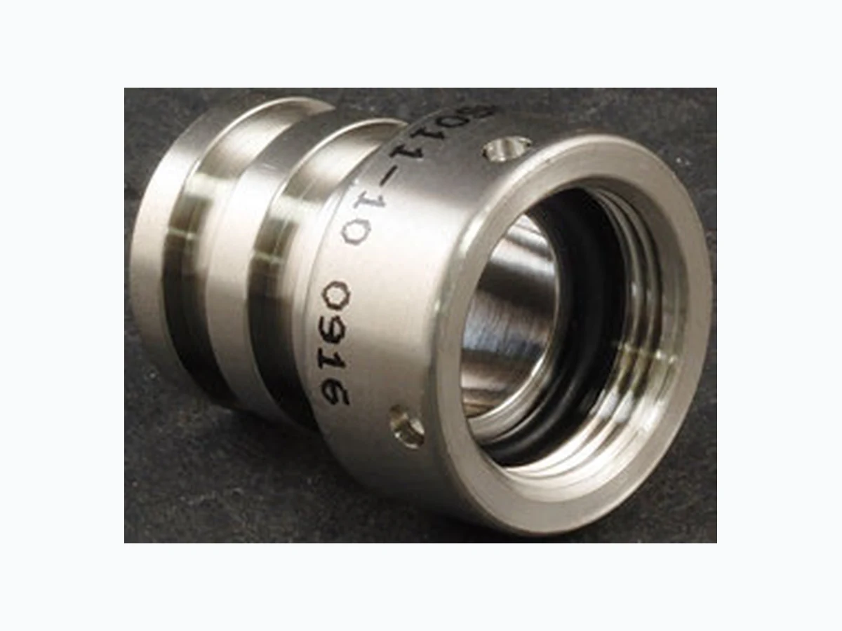
STAINLESS STEEL MOLDING ADAPTERS, STANDARD OR WITH OPTIONAL CABLE ENTRY DIAMETERS
Tips
To select the appropriate molding
adapter, consider the following basic suggestions to ensure a high integrity, quality molded termination:
Select a molding adapter which will provide adequate inside working room to accept the termination envelope, especially if there are shield terminations, splices, etc.
- If the termination is to be molded with neoprene or other material using a transfer molding process, select the molding adapter cable
entry diameter close to the outside diameter of the cable or termination envelope.
Notes
- Prior to use, lubricate O-rings with high grade silicone lubricant (Molykote M55 or equivalent). 2. Material: Adapter - stainless steel. O-ring - nitrile
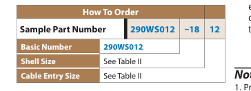
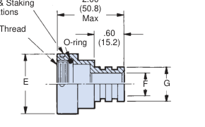
290WS012 OPTIONAL CABLE ENTRY DIAMETERS
290WS011 STANDARD
2.00
Tightening & Staking
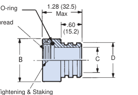
Indentations
A Thread
D
Indentations
© 2014 Glenair, Inc.
Series 22 Geo-Marine®
U.S. CAGE Code 06324
Printed in U.S.A.
GLENAIR, INC. • 1211 AIR WAY • GLENDALE, CA 91201-2497 • 818-247-6000 • FAX 818-500-9912
C-2
www.glenair.com
E-Mail: sales@glenair.com
Page 2


| Table I: 290WS011 Fixed Entry Dimensions | ||||
| Shell Size | A Thread Class 2B | B Dia Max | C Dia | D Dia |
| 10 | 5/8 - 24 UNEF | .855 (21.7) | .430 (10.9) | .670 (17.0) |
| 12 | 3/4 - 20 UNEF | .965 (24.5) | .535 (13.6) | .780 (19.8) |
| 14 | 7/8 - 20 UNEF | 1.090 (27.7) | .660 (16.8) | .905 (23.0) |
| 16 | 1 - 20 UNEF | 1.220 (31.0) | .785 (19.9) | 1.020 (25.9) |
| 18 | 1 1/8 - 16 UN | 1.370 (34.8) | .880 (22.4) | 1.135 (28.8) |
| 20 | 1 1/4 - 16 UN | 1.525 (38.7) | 1.005 (25.5) | 1.250 (31.8) |
| 22 | 1 3/8 - 16 UN | 1.655 (42.0) | 1.130 (28.7) | 1.383 (35.1) |
| 24 | 1 1/2 - 16 UN | 1.775 (45.1) | 1.255 (31.9) | 1.510 (38.4) |
| Table II: 290WS012 Variable Entry Dimensions | |||||
| Shell Size | A Thread Class 2B | E Dia Max | Max Entry | F Dia | G Dia |
| 10 | 5/8 - 24 UNEF | .855 (21.7) | .430 (10.9) | .670 (17.0) | |
| 12 | 3/4 - 20 UNEF | .965 (24.5) | 12 | .535 (13.6) | .780 (19.8) |
| 14 | 7/8 - 20 UNEF | 1.090 (27.7) | .660 (16.8) | .905 (23.0) | |
| 16 | 1 - 20 UNEF | 1.220 (31.0) | 16 | .785 (19.9) | 1.020 (25.9) |
| 18 | 1 1/8 - 16 UN | 1.370 (34.8) | .880 (22.4) | 1.135 (28.8) | |
| 20 | 1 1/4 - 16 UN | 1.525 (38.7) | 20 | 1.005 (25.5) | 1.250 (31.8) |
| 22 | 1 3/8 - 16 UN | 1.655 (42.0) | 1.130 (28.7) | 1.383 (35.1) | |
| 24 | 1 1/2 - 16 UN | 1.775 (45.1) | 24 | 1.255 (31.9) | 1.510 (38.4) |
| Table IV: Torque Values | |
| Entry No. | Torque ± 5 In. Lbs. |
| 10 | 80 |
| 12 | 100 |
| 14 | 120 |
| 16 | 120 |
| 18 | 140 |
| 20 | 140 |
| 22 | 140 |
| 24 | 150 |
Instructions for using cable molding adapters
- Slide 290WS011/012 adapter over cable 2. Prepare cable and wires 3. If using shrink sleeves, slide them over wire insulation and solder terminated wires to solder cup contacts; slide shrink sleeves to correct position and apply recommended heat. 4. Slide 290WS011/012 adapter and attach hand-tight to plug connector. 5. Use Plug Holding Tool (P/N 600-005) along with Hand Held Torque Wrench (P/N 600-076) and Spanner Wrench (P/N 600- 171) to tighten to recommended torque value.
© 2014 Glenair, Inc.
Series 22 Geo-Marine®
| Table V: Replacement O-Ring Part Numbers * | |
|---|---|
| Shell Size | Piston O-Ring |
| 10 | 2-014 |
| 12 | 2-016 |
| 14 | 2-018 |
| 16 | 2-020 |
| 18 | 2-022 |
| 20 | 2-024 |
| 22 | 2-026 |
| 24 | 2-028 |
| * Parker o-ring part numbers. Compound N674-70 or equivalent. | |
C
Please note that the “tightening/staking indentations” are on the 290WS011/012Adapter, NOT on the Marine Bronze Coupling Nut. The “holes” in the coupling nut retain the spring for the anti-decoupling feature of the cable plug. The TG70 Strap Wrench and the 600-076 Torque Wrench should be utilized to properly torque the cable/plug assembly to the appropriate receptacle
U.S. CAGE Code 06324
Printed in U.S.A.
GLENAIR, INC. • 1211 AIR WAY • GLENDALE, CA 91201-2497 • 818-247-6000 • FAX 818-500-9912
C-3