

 Download PDF
2863 BURKERT
Document overview
- Manufacturer or author: Provided By digicamel.com
- PDF pages: 13
Technical content
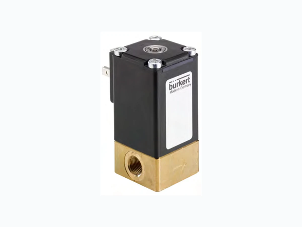
Visit product website DATA SHEET Type 8605 PWM control electro nics for electromagnetic proportional valves Type 2518 Cable Plug DIN EN 175301 803 Form A Type 8611 eCONTROL Universal contr oller 1000173851 | Standard | EU | en | 202109 | 06 Direct acting 2-way basic proportional valve
- High dynamics
- Orifice sizes DN 0.8 ... 4.0 mm
- Good range
- Optional: Explosion protected coil Type 2863 is an extremely compact solenoid control valve and is available with an orifice up to 4 mm. It is based on the standard version of Type 2873. It is used as an actuator in closed control loops (pressure, flow, temperature, etc.). Compared with the standard version, the valve is essentially of simpler construction and assembly and testing procedures are optimized, easing high volume series production with shorter delivery times. Product variants described in the data sheet may differ from the product presentation and description. Type descriptionCan be combined with Type 2863 © Christian Bürkert GmbH & Co. KG, Subject to alteration
2 | 12 Visit product website Table of contents 1. Gener al Technical Data 3 Cir cuit functions Approvals Materials 5. Dimensions 5 5.2. Sub-base body 5.3. ATEX version 6. Performance specifications 7 Determination of the 6.2. Exemplary characteristic curve of a proportional valve 7. Product operation 8 8. Or dering information 9 8.2. Recommendation regarding product selection 8.3. Bürkert product filter 8.4. Ordering chart Standard version ATEX/IECEx version 8.5. Ordering chart accessories Cable plug Type 2518, Form A according to DIN EN 175301 803 Control unit Type 8605
3 | 12 Visit product website 1. Gener al Technical Data Product properties Dimensions Detailed information can be found in chapter “5. Dimensions” on page 5. Material Body Brass, stainless steel Seal FKM, EPDM Performance data Typical values of positioning behaviour1.) Hysteresis < 5 % Reproducibility < % of end value2.) Response sensitivity < 1 % of end value2.) Setting range 1:25 Pressure range3.) 0…16 bar Nominal operating mode 100 % continuous oper ation Electrical data Operating voltage 24 V DC (12 V on request) Power consumption Maximal 9 W Maximum coil current4.) 420 mA (at 9 W and 24 V coil) PWM frequency5.) 400 Hz Medium data Operating medium Neutral gases, liquids on request Medium temperature - °C…+ (with FKM) °C…+ (with EPDM) Viscosity 21 mm2/s (21 cSt) P rocess/Port connection & communication Port connection size Sub-base, G G NPT NPT Electrical connection Cable plug Type 2518 acc. to DIN EN 175301 803 form A Detailed information can be found in chapter “Cable plug Type 2518, Form A accord- ing to DIN EN 175301 803” on page 10. Approvals and certificates Degree of protection IP65 Environment and installation Installation position Any, preferably actuator face up Ambient temperature Maximum 1.) Characteristic data of control behaviour depends on process conditions 2.) By flow measurement 3.) Pressure data: Overpressure with respect to atmospheric pressure, depending on nominal diameter, tightness seal or nominal pressure 4.) Maximum value: value depends on operating pressure 5.) PWM: pulse width modulation 2. Cir cuit functions Circuit functions Description 2 (A) 1 (P) Type: A, proportional control valve 2/2 way Direct acting Normally closed
4 | 12 Visit product website 3. Appr ovals Approvals Description Explosion protection ATEX: II G Ex mb IIC T4…T5 Gb II 2 D Ex mb IIIC T130 °C Db IECEx: Ex mb IIC T4…T5 Gb Ex mb IIIC T130 °C Db 4. Mat erials 4.1. Chemical Resistance Char t – Bürkert resistApp Bürkert resistApp – Chemical Resistance Chart You want to ensure the reliability and durability of the materials in your individual application case? V erify your combination of media and materials on our website or in our resistApp. Start Chemical Resistance Check
5 | 12 Visit product website 5. Dimensions 5.1. Thr eaded body Note: Dimensions in mm 17.5 64.5 A A B B 8.5 Threaded body G1 /8 NPT 1/8 22.5 69.5 B B A A 30.5 4x M4 8 4x M4 8 Threaded body G 1/4 NPT 1/4 Body version Threaded body A G ¼ NPT ¼ G ⅛ NPT B 12 10 8 7
6 | 12 Visit product website 5.2. Sub-base body Note: Dimensions in mm DN 4x 4 8.9 27.8 16.5 P Sub-base body FK01 5.3 2 x M4 30.5 3.7 6.3 P Sub-base body FB01
7 | 12 Visit product website 5.3. A TEX version Note: Dimensions in mm Length according to order Standard length 3000 10.9 10.6 85.8 min. R30 6.2 10.8 6. P erformance specifications 6.1. Flow char acteristic Determination of the KV value Pressure drop KV value for liquids KV value for gases [m3/h] [m3/h] Sub-critical p2 > 2 = Q ρ Δp1000 = Q 514 QN ρNT1 Δ pp2 Supercritical p2 < 2 = Q ρ Δp1000 = Q QN ρNT1 257 p1 KV Flow coefficient [m3/h]1.) QN Standard flow rate [mN 3/h]2.) p1 Inlet pressure [bar]3.) p2 Outlet pressure [bar]3.) ∆p Differential pressure p1...p2 [bar] ρ Density [kg/m3] ρN Standard density [kg/m3] T1 Medium temperature [(273+t)K] 1.) Measured for water, 1 bar over the value 2.) At reference conditions 1.013 bar and (273 3.) Absolute pressure
8 | 12 Visit product website 6.2. Ex emplary characteristic curve of a proportional valve Note: In continuous flow applications, the choice of an appropriate valve size is much more important than with on/off valves. The optimum siz e should be selected such that the resulting flow in the system is not unnecessarily reduced by the valve. However, a sufficient par t of the pressure drop should be taken across the valve even when it is fully opened. Recommended value: Δpvalve > 25 % of t otal pressure drop within the system Otherwise, the ideal, linear valve curve characteristic is changed. If the differential pressure (difference between inlet and outlet pressure) exceeds half the value of the nominal pressure discontinuities may occur. For that reason take advantage of Bürkert competent engineering services during the planning phase! 1.0 0.9 0.8 0.7 0.6 0.5 0.4 0.3 0.2 0.1 0.0 K V KVS 0 5 10 [V] 4 12 20 [mA] 0 10 20 [mA]7. Product operation 7.1. Control unit Valve control takes place through a PWM signal (pulse-width modulation). The duty cycle of the PWM signal determines the coil curr ent and hence the position of the plunger. The Bürkert control electronics Type 8605 (see relevant data sheet Type 8605 ) converts an analogue signal to a reference value cor responding to the valve type PWM signal and provides additional functions such as temperature compensation (coil heating), ramp function and the adjustment of min. and max. duty cycle/coil current for the control range. Please note the sizing comments for such a control valve in chapter “6.2. Exemplary characteristic curve of a proportional valve” on page 8.
9 | 12 Visit product website 8. Or dering information 8.1. Bürk ert eShop – Easy ordering and quick delivery Bürkert eShop – Easy ordering and fast delivery You want to find your desired Bürkert product or spare part quickly and order dir ectly? Our online shop is available for you 24/7. Sign up and enjoy all the benefits. Order online now 8.2. Recommendation r egarding product selection Note:
- Please use the “Product Inquiry Form” at the end of this data sheet for the specifications of the device configuration and send us a copy of the inquiry with information about the application.
- Please note the chapter “6.2. Exemplary characteristic curve of a proportional valve” on page 8 on product selection. 8.3. Bürk ert product filter Bürkert product filter – Get quickly to the right product Y ou want to select products comfortably based on your technical requirements? Use the Bürkert product filter and find suitable articles for your application quickly and easily Try out our product filter 8.4. Or dering chart Standard version Note:
- All valves with FKM seal
- Please note that the cable plug must be ordered separately, see “Cable plug Type 2518, Form A according to DIN EN 175301 803” on page 10 or separate data sheet for Type 2518 Circuit function Orifice Port connec- tion1.) KVS value water2.) Nominal pressure 3.) Article no. brass body Article no. stainless steel body[mm] [m3/h] [bar] A, proportional control valve 2/2 way Direct acting Normally closed 2 (A) 1 (P) 0.8 G ⅛ 0.018 16 275060 275063 1.2 G ⅛ 0.040 12 249140 275064 1.5 G ⅛ 0.060 10 249141 275065 2.0 G ⅛ 0.100 8 254182 275066 G ¼ 0.100 8 255699 276517 2.5 G ¼ 0.150 5 275061 275067 3.0 G ¼ 0.220 3.5 275062 275068 4.0 G ¼ 0.320 2 251831 255700 1.) NPT and Sub-base on request 2.) Flow rate value for water, measured at and 1 bar pressure differential over a fully opened valve. 3.) Pressure data: Overpressure with respect to atmospheric pressure.
10 | 12 Visit product website ATEX/IECEx version Note:
- All valves with FKM seal and ATEX version with m connection cable.
- For detailed information regarding ATEX and IECEx approvals see “3. Approvals” on page 4
- Please use the “Product Inquiry Form” at the end of this data sheet for the specifications of the device configuration and send us a copy of the inquiry with information about the application. Circuit function Orifice Port connec- tion1.) KVS value water2.) Nominal pressure 3.) Article no. brass body Article no. stainless steel body[mm] [m3/h] [bar] A, proportional control valve 2/2 way Direct acting Normally closed 2 (A) 1 (P) 0.8 G ⅛ 0.018 8 343042 On request 1.2 G ⅛ 0.040 6 343044 On request 1.5 G ⅛ 0.060 6 337721 On request 2.0 G ⅛ 0.100 6 310840 On request 2.5 G ¼ 0.150 2.5 343045 On request 3.0 G ¼ 0.220 2 343047 On request 4.0 G ¼ 0.320 1 343049 On request 1.) NPT and Sub-base on request 2.) Flow rate value for water, measured at and 1 bar pressure differential over a fully opened valve. 3.) Pressure data: Overpressure with respect to atmospheric pressure. Further versions on request Material Other seal materials Analytical Oxygen version, Parts oil , fat and silicon free Approval ATEX IECEx Orifice Special valve orifice Coil Other coil power Specific, power setting for lower pressure Other operating voltages 8.5. Or dering chart accessories Cable plug Type 2518, Form A according to DIN EN 175301 - 803 Not Further versions see data sheet Type 2518 Cable plug Dimensions Version Voltage Article no. ca. 51 35.7 3.5 1.5 29.2 Ø 19 29.2 Without circuitry (AC/DC) 0…250 V A C/DC 314802
11 | 12 Visit product website Control unit Type 8605 Note: Further versions see data sheet Type 8605 . Version Max. coil current range Type 2863 Type 2863 Article no. [mA] 24 V DC 12 V DC Cable plug with PG cable gland 200…1000 x x 316530 Cable plug with M12 connection 200…1000 x x 316528 Cable plug with PG cable gland 500…2000 – x 316529 Cable plug with M12 connection 500…2000 – x 316526 Cable plug with PG cable gland without operating element 200…1000 x x 316521 Cable plug with M12 connection without operating element 200…1000 x x 316522 Cable plug with PG cable gland without operating element 500…2000 – x 316523 Cable plug with M12 connection without operating element 500…2000 – x 316525 Standard rail 200…1000 x x 316532 Standard rail 500…2000 – x 316533
Bürkert – Close to You Austria Belgium Czech Republic Denmark Finland France Germany Italy Netherlands Norway Poland Spain Sweden Switzerland Turkey United Kingdom China Hong Kong India Japan Korea Malaysia Philippines Singapore Taiwan South Africa Russia United Arab Emirates Brazil Uruguay Canada USA Australia New Zealand Credits, © and concept: Christian Bürkert GmbH & Co. KG | Photographs: Marc Eggimann Fotografie - 4051 Basel | Scanner GmbH - Werbeagentur Künzelsau -
74653 Künzelsau
www.burkert.com
1 | 1Visit this product area on the website © Christian Bürkert GmbH & Co. KG, subject to change Product Enquiry Form - Proportional valve Thank you for your interest in our products! In order to provide you with optimum advice, please fill out the following form and send it to your Bürkert r epresentative or e mail address: info@burkert.com. All information submitted will of course be kept strictly confidential. Please fill in the required fields! * *Note: The interactive functions of this PDF may be restricted depending on the PDF reader used. Personal Information Company Contact person Customer no. Department Street Postcode / Town Telephone no. Email Delivery Quantity Required delivery date Operating data Function (Function of the control valve in the process process description) Operating medium Type of medium Fluid S team Gas Supply voltage V Ambient t emperature (max.) tu max = ºC / ºF Fluidic data Flow range Q Nom min. max. unit Inlet pressure at QNom p1 = barg1.) Outlet pressure at QNom p2 = barg1.) Max. inlet pressure p1max = barg1.) Medium temperature (min./ max.) tm min = tm max = ºC / ºF Port connection G (DIN ISO 228/1) NPT (ANSI B1.2) Flange Other 1.) Please indicate all pressure values as overpressure to atmospheric pressure [barg] (g = relative pressure) Material specifications Body S tainless steel Br ass Other Seals F K M EPDM Other Approvals / Conformities UL/UR, KTW W270, DVGW Gas, ATEX/IECEx, EAC, etc. Additional Requirements / Comment