
25PT_14 NELLSEMI
Document overview
- Manufacturer or author: Provided By www.digicamel.com(FREE DATASHEET DOWNLOAD SITE)
- PDF pages: 5
Technical content
SEMICONDUCTOR 25PT Series RoHS RoHS Stansard SCRs, 25A Main Features Symbol Value Unit IT(RMS) V /VDRM RRM IGT 25 A V mA4 to 40 600 to 1200
DESCRIPTION
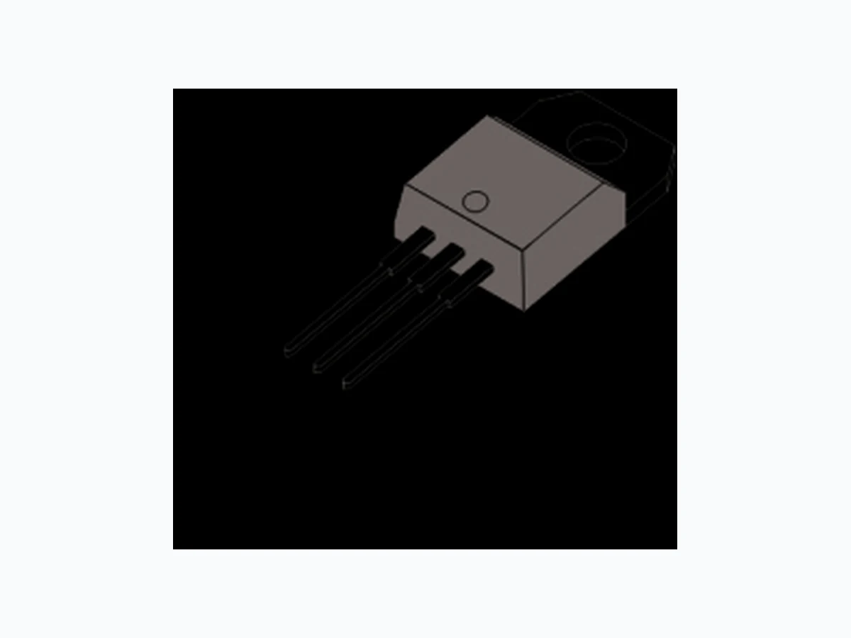
TO-220AB (Non-lnsulated) 1 2 3 TO-220AB (lnsulated) (25PTxxA) (25PTxxAI) www.nellsemi.com The 25PT series of silicon controlled rectifiers are high performance glass passivated technology, and are suitable for general purpose applications. Using clip assembly technology, they provide a superior performance in surge current capabilities. 2TO-263 (D PAK) (25PTxxH) SYMBOL IT(RMS) RMS on-state current full sine wave ITSM Non repetitive surge peak on-state current (full cycle, T initial = 25°C)j A I t22I t Value for fusing 450 2A s dI/dtCritical rate of rise of on-state current 50 IGMPeak gate current PG(AV)Average gate power dissipation TstgStorage temperature range Operating junction temperature range - 40 to + 150 - 40 to + 125 ºC A/µs A A W UNITVALUE 300F =50 Hz F =60 Hz t = 20 ms t = 16.7 ms t = 10 msp F = 60 Hz T =125ºCj T = 125ºCj T = 125ºCj T = 20 µsp Tj ABSOLUTE MAXIMUM RATINGS PARAMETER TEST CONDITIONS V600 to 1200 T =125ºCj VDRM VRRM Repetitive peak off-state voltage Repetitive peak reverse voltage (180° conduction angle ) Average on-state current (180° conduction angle) IT(AV) 16 A I = 2xl , t ≤100nsG GT r TO-263/TO-220AB TO-220AB insulated Tc=100°C Tc=83°C Maximum gate power PGM W10T =20µsp T = 125ºCj TO-263/TO-220AB TO-220AB insulated Tc=100°C Tc=83°C 314 G 3(G) 1(K) 2(A)
Page 2 of 5www.nellsemi.com Note: xx = voltage , y = sensitivity 25PTxxxx Unit IGT VGD IH mA dV/dt VTM IDRM IRRM mA IL V = 12V, R = 33ΩD L V = V , R = 3.3KD DRM L Ω R = 220ΩGK I = 500mA, Gate openT I = 1.2×IG GT V = 67% V Gate openD DRM, 0.2 500 mA V V mA V/µs I = 50A, T t = 380µsP T = 125°Cj T = 25°Cj T = 25°Cj V µA ELECTRICAL SPECIFICATIONS (T = 25 ºC unless otherwise specified)J TEST CONDITIONS SYMBOL V =V , V =VD DRM R RRM 1.6 2R = 220ΩGK Max. Max. Min. Max. Min. Min. Max. Max. Max. THERMAL RESISTANCE Rth(j-c) Junction to case (DC) Rth(j-a) Junction to ambient 1.0 °C/W °C/W UNITVALUESYMBOL Parameter 2D PAK/TO-220AB TO-220AB insulated TO-263( PAK)2D TO-220AB/TO-220AB insulated 2.0 VGT V0.77Vto T = 125°Cj PRODUCT SELECTOR PART NUMBER VOLTAGE (xx) SENSITIVITY 600 V 40 mA 1000 V 25PTxxA/25PTxxAl 25PTxxH VV 800 V V PACKAGE TO-220AB V V 2D PAK 40 mA
ORDERING INFORMATION
ORDERING TYPE MARKING PACKAGE WEIGHT ,BASE Q TY DELIVERY MODE TO-220AB 2.0g 50 Tube 25PTxxAI-y 25PTxxAI-y 2.3g 50 Tube 25PTxxH-y 25PTxxH-y 2TO-263(D PAK) 2.0g 50 TO-220AB (insulated) Tube Rd mΩT = 125°Cj T = 125°Cj T = 125°Cj Max. Max. 14 2S = 1 cm Threshold Voltage Dynamic Resistance Min. 1.3 S=Copper surface under tab D 10 40 100 150 V 1200 V V V V V VV VV V V 25PTxxA-D/25PTxxAl-D 25PTxxH-D 4~10 mA 4~10 mA TO-220AB 2D PAK
Page 3 of 5www.nellsemi.com ORDERING INFORMATION SCHEME SCR series Package type Current Voltage Code A = TO-220AB (non-insulated) AI = TO-220AB ( insulated) 25 = 25A, IT(RMS)
25 PT 06
06 = 600V 2H = TO-263 (D PAK) 08 = 800V 10 = 1000V Fig.1 Maximum average power dissipation versus average on-state current. Fig.2 Average and DC on-state current versus case temperature. Fig.3 Average and DC on-state current versus ambient temperature. Fig.4 Relative variation of thermal impedance versus pulse duration.(D²PAK, and TO-220AB) P (W) 0 2 4 6 8 10 12 0 25 50 75 100 125 0.0 0.5 1.0 1.5 2.0 2.5 3.5 3.0 l (A)T(AV) l (A)T(AV) 0 25 50 75 100 125 K=[Z /R ]th th 1.00 0.10 0.01 1E-3 1E-2 1E-1 1E+0 1E+1 1E+2 5E+2 - D I SensitivityGT 12 = 1200V D = 4~10mA Blank = 4~40mA α 360° I (A)T(AV) 14 16 α=180° D.C. TO-220ABins TO-220AB D²PAK T (°C)case T (°C)amb α=180° D.C. TO-220ABins TO-220AB D²PAK Z (j-c)th Z (j-a)th t (s)P 16 = 1600V
Fig.7 Surge peak on-state current versus number of cycles. Fig.5 Relative variation of thermal impedance versus pulse duration. (TO-220AB ins) 1.0E-02 l ,l ,l [T ] / l ,l ,l [T =25°C]GT H L j GT H L j I (A)TM 0.0 0.5 1.0 1.5 2.0 2.5 -40 100 Fig.8 Non-repetitive surge peak on-state current , and corresponding values 2 of l t 1 10 100 1000 2000 100 1000 0.01 0.10 1.00 10.00 Fig.9 On-state characteristics (maximum values) Page 4 of 5www.nellsemi.com t (s)P Zth(j-a) Zth(j-c) lGT I & IH L T (°C)j -20 0 20 40 60 80 120 140 T =10msp One cycle Non repetitive T initial = 25°Cj Repetitive T = 83 °Ccase Number of cycles 100 150 200 250 300 350 lTSM T initial = 25°Cj 2l t dl/dt limitattion Sinusoidal pulse width t (ms)p T max.:j V = 0.77Vto R = 14m dV (V)TM 2S(cm ) Epoxy printed circuit board F copper thickness = 35 µm 100 1000 0 4 128 16 20 24 28 32 36 40 Fig.10 Thermal resistance junction to versus copper surface 2 (D PAK) ambient under tab Fig.6 Relative variation of gate trigger holding, and latching currents versus junction temperature. I (A), l²t (A²s)TSMI (A)TSM K=[Z /R ]th th 1.0E-01 1.0E+01 R (j-a)(°C/W)th R4,
(G)3 1(A1) (A2) 2.87 (0.113) 2.62 (0.103) 9.40 (0.370) 9.14 (0.360) 10.54 (0.415) MAX. 16.13 (0.635) 15.87 (0.625) PIN 4.06 (0.160) 3.56 (0.140) 1.45 (0.057) 1.14 (0.045) 2.67 (0.105) 2.41 (0.095) 2.65 (0.104) 2.45 (0.096) 5.20 (0.205) 4.95 (0.195) 0.90 (0.035) 0.70 (0.028) 3.91 (0.154) 3.74 (0.148) 4.70 (0.185) 4.44 0.1754 ( ) 1.39 (0.055) 1.14 (0.045) 3.68 (0.145) 3.43 (0.135) 8.89 (0.350) 8.38 (0.330) 29.16 (1.148) 28.40 (1.118) 14.22 (0.560) 13.46 (0.530) 0.56 (0.022) 0.36 (0.014) 2.79 (0.110) 2.54 (0.100) 15.32 (0.603) 14.55 (0.573) TO-220AB 25PT Series 2TO-263(D PAK) 2.79 (0.110) 0.36 (0.014) 2.79 (0.110) 2.29 (0.090) 1.40 (0.055) 1.19 (0.047) 0 to 0.254 (0 to 0.01) 1.40 (0.055) 1.14 (0.045) 4.83 (0.190) 4.06 (0.160) 10.45 (0.411) 9.65 (0.380) 6.22 (0.245) 9.14 (0.360) 8.13 (0.320) 15.00 (0.591) 0.940 (0.037) 0.686 (0.027) 2.67 (0.105) 2.41 (0.095) 5.20 (0.205) 4.95 (0.195) 15.85 (0.624) 3.56 (0.140) 0.53 (0.021) Case Style Page 5 of 5www.nellsemi.com