

 Download PDF
254 CTS
Document overview
- PDF pages: 2
Technical content
Page 1

®
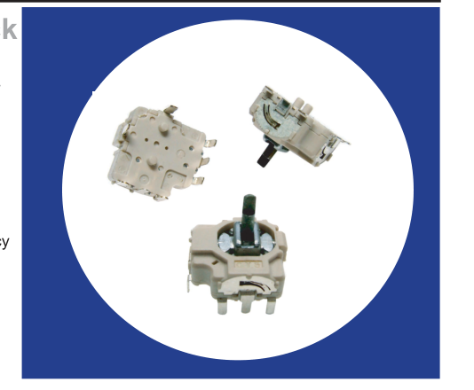
Two Axis, Micro-stick
Controller With
Optional Momentary
Switch
Features
- Sub-Compact Size: 11x11x5 (mm)
- Long Life 1 Million Cycles
- Provides excellent electrical accuracy
through patented mechanism
- Optional momentary switch is
operational at all rotations
- RoHS compliant
Electrical and Mechanical Specifications
Potentiometer 1 & 2
Resistance Range 10 K ohms through 100 K ohms Resistance Tolerance Standard: ±30% Special: ± 20% available
Dielectric Strength 250 VAC 50/60 Hz for 1 minute Insulation Resistance 100 Megohms @ 250 VDC Operational Torque 120 ±50 gf-cm Power Rating 0.0125 watt @ 50°C, derated to no load @ 85°C Maximum Operating Voltage 50 VAC or 5 VDC maximum Angle of Rotation 60° maximum Life 1,000,000 cycles
Available Switch
Type Momentary Contact Resistance 100 milliohms maximum Maximum Contact Resistance 200 milliohms maximum after 200,000 cycles switching 5mA @ 5VDC
Insulation Resistance 100 Megaohms minimum @ 100 VDC Operational Force 800±200 gf Power Rating 5 VDC, 5 mA maximum Travel
0.8±0.2mm
Switch Life 200,000 cycles
Taiwan patent No. I279822. Patent Pending in US, Japan & China
1 - 2 © 2007 CTS Corporation. All rights reserved. Information subject to change.
05/24/07
CTS Electronic Components
www.ctscorp.com
Page 2
Electrical and Mechanical Specifications
Potentiometer 1 & 2
Operating Temperature
Operating: -10°C to +70°C
Mounting Information
Through Hole or SMD Terminal
CTS Series 254
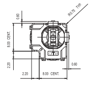
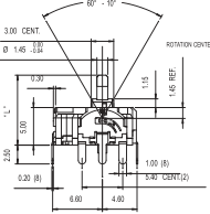
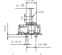
DIMENSION: mm
SMD Style
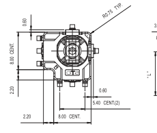
0° 60° - 10°
| 3.00 CENT. Ø 1.45- 00 .. 00 40 ROTAT REF. 1.15 0.30 (4) 1.45 | |
| 5.00 | |
ROTATION CENTER
Through Hole Style
0°
Ordering Information
B
T
254
Soldering Heat Resistance
260±5°C for 5 seconds
5.15 REF.
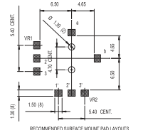
RECOMMENDED SURFACE MOUNT PAD LAYOUTS
2'
2 VR1
VR2
a
CIRCUIT
b
3
3' 1'
1
5.15 REF.
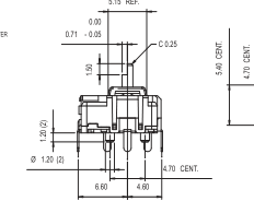
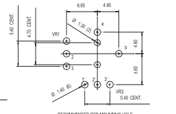
RECOMMENDED PCB MOUNTING HOLE
103
C 50 A
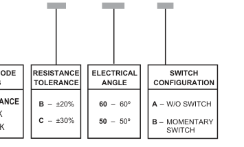
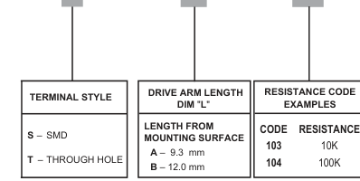
STANDARD PART (QUICK DELIVERY, IVORY COLOR) - 254TA103C50A, 254TA103C50B, 254SA103C50A, 254SA103C50B
© 2007 CTS Corporation. All rights reserved. Information subject to change.
2 - 2
05/24/07
CTS Electronic Components
www.ctscorp.com