

 Download PDF
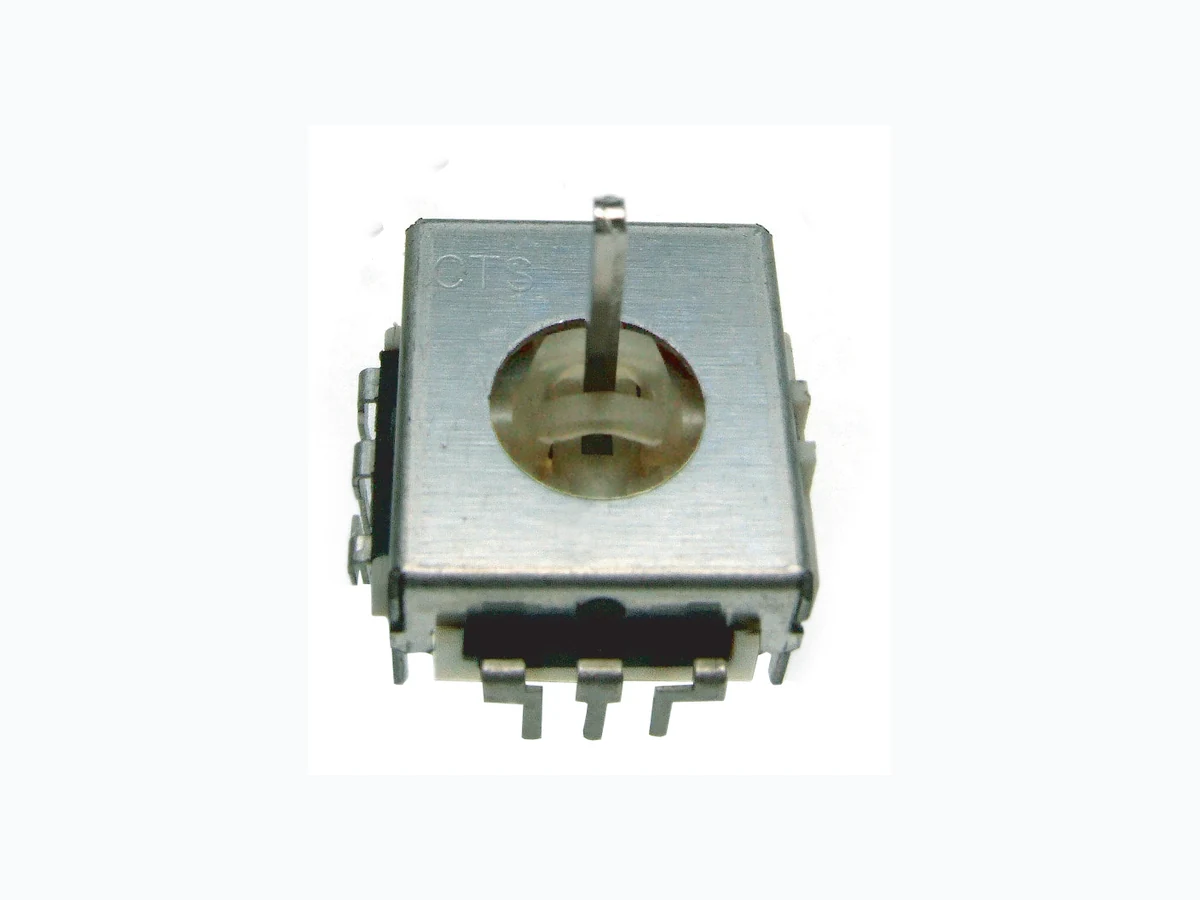
253 CTS
Document overview
- PDF pages: 2
Technical content
Page 1

®
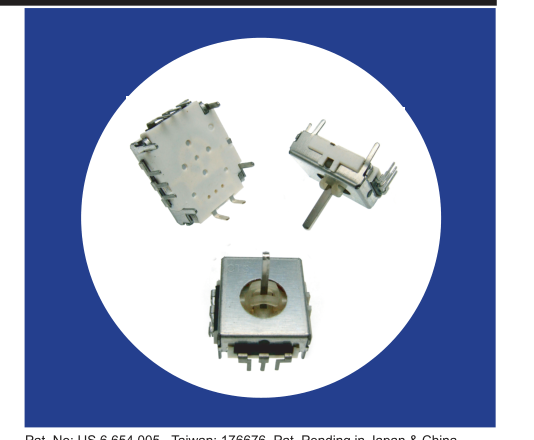
Two Axis, Ministick
Controller With
Optional Momentary
Switch
Features
- Compact Size: 20x18x6mm (.79"x.71"x.24")
- Long Life 1 Million Cycles
- Optional momentary switch is
operational at all rotations
- Sturdy metal case with convenient
mounting tabs
- RoHS compliant
Electrical and Mechanical Specifications
Potentiometer 1 & 2
Resistance Range 10 K ohms through 200 K ohms Resistance Tolerance Standard: ±30% Special: ±10% and ± 20% available
Insulation Resistance 100 Megaohms @ 250 VDC Operation Torque 180 ±50 gf-cm (2.5 ±0.7 in-oz) Power Rating 0.0125 watt @ 50°C, derated to load @ 85°C Maximum Operating Voltage 50 VAC or 5 VDC maximum Angle of Rotation 54° maximum Life Standard: 1,000,000 cycles Special: Consult CTS
RoHS Compliance Compliant with European Union RoHS Directive
Pat. No: US 6,654,005 . Taiwan: 176676. Pat. Pending in Japan & China
Available Switch
Type Momentary Contact Resistance 100 milliohms max Maximum Contact Resistance 200 milliohms max after 500,000 cycles switching 5mA @ 5VDC Dielectric Strength 250 VAC 50/60 Hz for 1 minute Insulation Resistance 100 Megaohms min @ 100 VDC Operational Force 1,200±260 g Power Rating 5 VDC, 5 mA maximum Travel +0.5 0.5 mm -0.4 Switch Life 500,000 cycles
© 2007 CTS Corporation. All rights reserved. Information subject to change.
1 - 2
01/24/07
CTS Electronic Components
www.ctscorp.com
Page 2
Electrical and Mechanical Specifications
Potentiometer 1 & 2
Operating Temperature
Operating: -10°C to +70°C
Mounting Information
PC Terminals
CTS Series 253
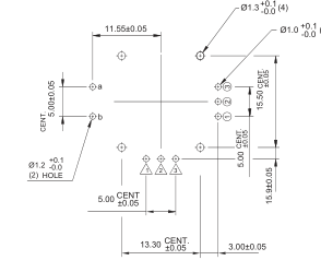
+0.1 (6)
Soldering Conditions
Wave - up to 5 seconds at 260°C No Solder or flux on component side of board
Caution
Please use extra mechanism to restrict rotational angle at less than 54 degree or there will be bumpy or rugged rotational feeling
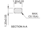
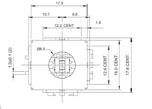
SCALE : 5X
RECOMMENDED CUSTOMERS
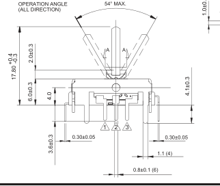
a
MOUNTING HOLE DETAIL VIEWED
L
b
FROM MOUNTING SIDE
SWITCH CIRCUI T DIAGRAM
DIMENSION: mm
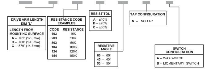
Ordering Information
253 B 103 C 60 N A
© 2007 CTS Corporation. All rights reserved. Information subject to change.
2 - 2
01/24/07
CTS Electronic Components
www.ctsco r p . c o m