
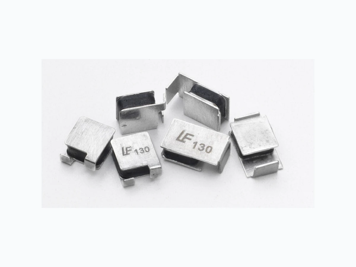
250S130_0911 LITTELFUSE
Document overview
- Manufacturer or author: Provided By digicamel.com
- PDF pages: 5
Technical content
Features
Applications
- RoHS Compliant, Directive 2002/95/EC
- Lead-Free & Halogen-Free
- Low resistance
- Compatible with telecom standards
- Helps meets ITU K.20, K.21/Telcordia standards
- Excellent solder joint inspectability
- High voltage 250S Series
- Customer Premises Equipment (CPE)
- Central Office (CO)/ telecom centers
- LAN/WAN equipment
- Access equipment
Revised: November 30, 2009 ©2009 Littelfuse, Inc. POL YFUSE® Resettable PTCs Surface Mount > 250S Series 250S Series Specifications are subject to change without notice. Please refer to www.littelfuse.com/series/250S.html for current information. Ambient Operation Temperature -40°C -20°C 0°C 23°C 40°C 50°C 60°C 70°C 85°C Part Number Hold Current (A) T emperature Rerating T emperature Rerating CurveAverage Time Current Curves The average time current curves and Temperature Rerating curve performance is affected by a number or variables, and these curves provided as guidance only. Customer must verify the performance in their application. 200.00 160.00 120.00 80.00 40.00 0.00 Device Ambient Temperature ºC Percentage of rated current % Protection Application Guide Region/ Specification Application Device Selection South America/ Asia/Europe ITU K.45 Access network equipment Remote terminal Repeaters WAN equipment Cross –connect 250S130 250S130V 250S130-RA 250S130-RB 250S130-RC South America/ Asia/Europe ITU K.21 Customer and IT equipment Analog modems ADSL, xDSL Phone sets, PBX systems Internet appliances POS terminals 250S130 250S130V 250S130-RA 250S130-RB 250S130-RC South America/ Asia/Europe ITU K.20 Central Office POTS/ISDN linecards T1/E1/J1 linecards ADSL/VDSL splitters CSU/DSU 250S130 250S130V 250S130-RA 250S130-RB 250S130-RC Agency Specification Selection Guide For T elecom and Networking Applications Product Lightning Power Cross 250S130 250S130V 250S130-RA 250S130-RB 250S130-RC ITU K.20/21/45 – 1 .5kV 10/700μs ITU K.20/21/45 – 230Vac, 10Ω 250S 0.10 100 1000 0.1 1 10 100 Current in Amperes Time in Seconds 0.13A
59©2009 Littelfuse, Inc. Revised: November 30, 2009 POL YFUSE® Resettable PTCs 250S Series Surface Mount > 250S Series 250S Series Specifications are subject to change without notice. Please refer to www.littelfuse.com/series/250S.html for current information. Soldering Parameters Profile Feature Pb-Free Assembly Average Ramp-Up Rate (TS(max) to TP) 3°C/second max Pre Heat: Temperature Min (Ts(min)) 150°C Temperature Max (Ts(max)) 200°C Time (Min to Max) (ts) 60 – 180 secs Time Maintained Above: Temperature (TL) 217°C Temperature (tL) 60 – 150 seconds Peak / Classification Temperature (TP) 260 +0/-5 °C Time within 5°C of actual peak Temperature (tp) 20 – 40 seconds Ramp-down Rate 6°C/second max Time 25°C to peak Temperature (TP) 8 minutes Max. -- All temperature refer to topside of the package, measured on the package body surface -- If reflow temperature exceeds the recommended profile, devices may not meet the performance requirements -- Recommended reflow methods: IR, vapor phase oven, hot air oven, N2 environment for lead -- Recommended maximum paste thickness is 0.25mm (0.010 inch) -- Devices can be cleaned using standard industry methods and solvents -- Devices can be reworked using the standard industry practices Environmental Specifications Operating/Storage T emperature -40°C to +85°C Maximum Device Surface T emperature in T ripped State 125°C -/+10ºC Passive Aging +85°C, 1000 hours Humidity Aging +85°C, 85%,R.H.,1000 hours Thermal Shock MIL–STD–202F , Method 107G +125°C to -55°C 10 times Solvent Resistance MIL–STD–202, Method 215F Moisture Sensitivity Level Level 1, J–STD–020C Physical Specifications T erminal Material Solder-Plated Copper (Solder Material: Matte Tin(Sn)) Lead Solderability Meets EIA Specification RS186-9E, ANSI/ J-STD-002 Category 3.
Revised: November 30, 2009 ©2009 Littelfuse, Inc. POL YFUSE® Resettable PTCs Surface Mount > 250S Series 250S Series Specifications are subject to change without notice. Please refer to www.littelfuse.com/series/250S.html for current information. Dimensions Part Number ABCDE Material FG H Inch mm Inch mm Inch mm Inch mm Inch mm Inch mm Inch mm Inch mm A D C E B F H G G Soldering Pad Layout Part Number Ordering Number I hold (A) I hold Code Packaging Option Quantity Quantity & Packaging Code 250S130 250S130DR 0.13 130 Tape and Reel 1500 DR 250S130V 250S130VDR 0.13 130 Tape and Reel 1500 DR 250S130–RA 250S130–RADR 0.13 130 Tape and Reel 1500 DR 250S130–RB 250S130–RBDR 0.13 130 Tape and Reel 1500 DR 250S130–RC 250S130–RCDR 0.13 130 Tape and Reel 1500 DR Packaging Part Ordering Number System
250 S 130 -RA D R
(Refer to Electrical Characteristics Table) QUANTITY CODE: D=1500 R: Tape & Reel (BLANK) = Horizontal / 4-13Ω resistance range V = Vertical / 4-13Ω resistance range -RA = Horizontal / 6.5-10Ω resistance range -RB = Horizontal / 9-13Ω resistance range -RC = Horizontal / 7-11Ω resistance range PEAK VOLTAGE RATING OPTION CODE Part Number AB C D EF Material GH I J Inch mm Inch mm Inch mm Inch mm Inch mm Inch mm Inch mm Inch mm Inch mm Inch mm CC E B D A G I H H G J Soldering Pad Layout F
61©2009 Littelfuse, Inc. Revised: November 30, 2009 POL YFUSE® Resettable PTCs 250S Series Surface Mount > 250S Series 250S Series Specifications are subject to change without notice. Please refer to www.littelfuse.com/series/250S.html for current information. TAPE SPECIFICATIONS: EIA-481-1 (mm) REEL DIMENSIONS: EIA-481-1 (mm) D1 1 .00(MIN) C Ø340+/- 1 .0 Tmax 0.4 +/- 0.10 K0 3.4 +/- 0.15 Leader Min. 300 Trailer Min. 300 T ape and Reel Specifications T ape and Reel Diagram F W CD H K0 B0A0 T F W